Blade retention arrangement

a technology of retaining arrangement and blade, which is applied in the direction of marine propulsion, liquid fuel engine, vessel construction, etc., to achieve the effect of convenient installation, simple design, and easy and cost-effective us

Inactive Publication Date: 2007-07-17
ROLLS ROYCE DEUT LTD & CO KG
View PDF6 Cites 13 Cited by
  • Summary
  • Abstract
  • Description
  • Claims
  • Application Information

AI Technical Summary

Benefits of technology

[0009]The present invention provides for a favorable introduction of the centrifugal forces beneath the blade root and, thus, for a low weight of blade and disk. This also contributes positively to the life of the entire arrangement.
[0017]It is particularly advantageous if the retaining ring is provided with an anti-rotation lock which prevents the retaining ring from moving circumferentially. The anti-rotation lock is, in a preferred form, provided as a radial tang on the retaining ring and is preferably arranged at an end of said ring. This enables the retaining ring to be inserted and secured by way of the anti-rotation lock.

Problems solved by technology

Each of these embodiments has its specific disadvantages, these calling either for particular design prerequisites or being incompatible with specific design solutions.

Method used


Image

  • Blade retention arrangement
  • Blade retention arrangement
  • Blade retention arrangement

Examples


Embodiment Construction

[0027]This detailed description should be read in conjunction with the summary of the invention above.

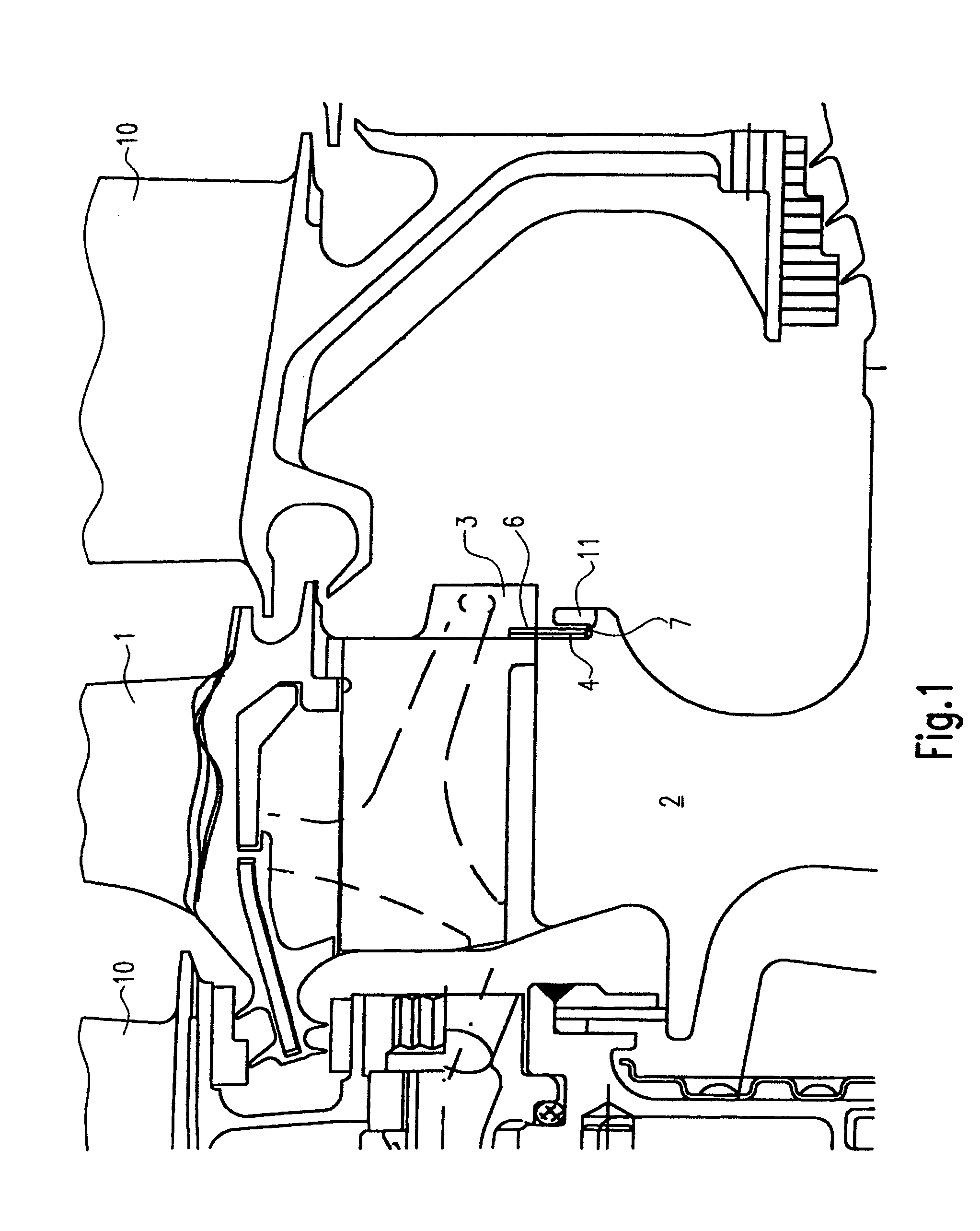
[0028]FIG. 1 is a simplified representation of a rotatably borne disk 2 of a gas turbine engine carrying several blades 1. Adjacent stator vanes are designated with the reference numeral 10. As regards the general design, reference is made to the state of the art, so that a further description can be dispensed with herein.

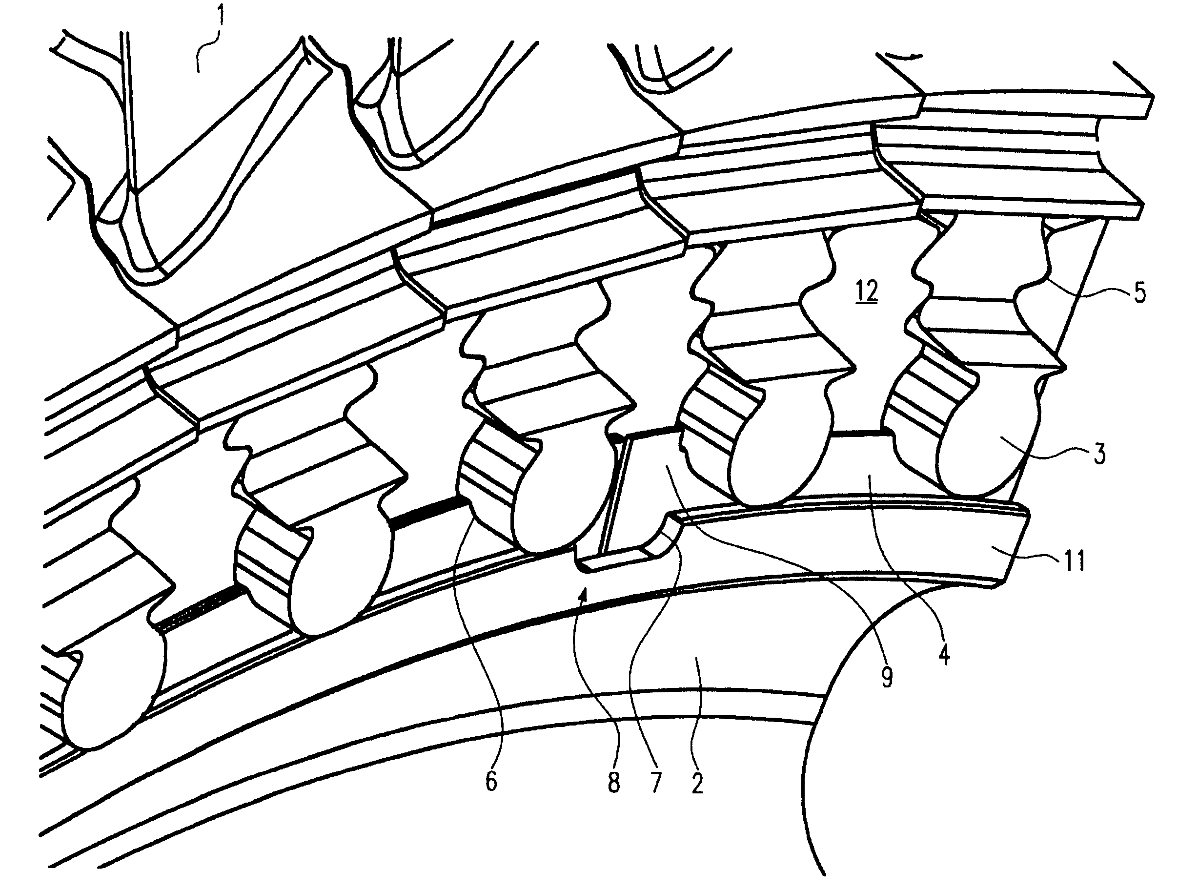
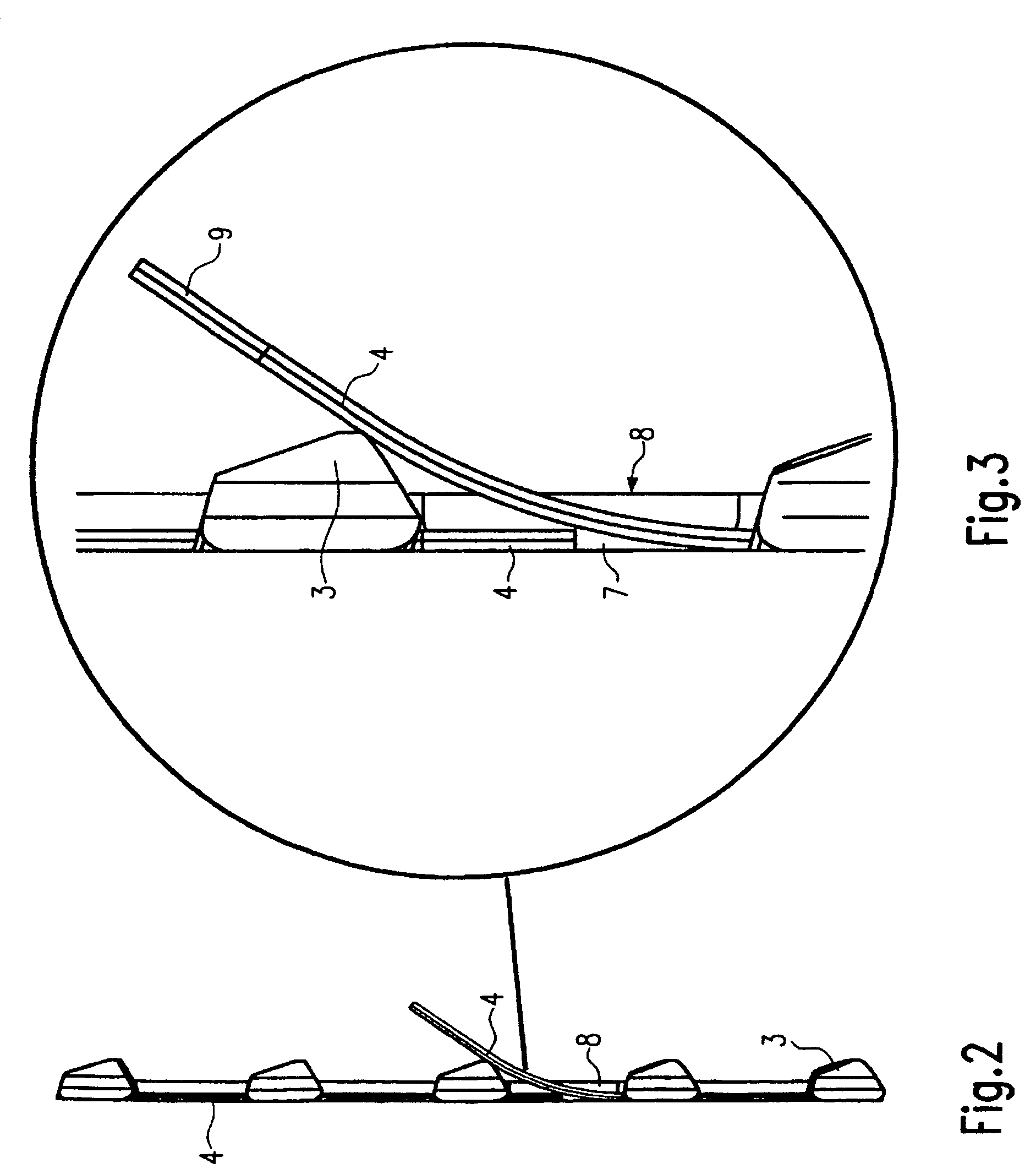
[0029]As shown in FIGS. 4 and 5, in particular, the blades 1 each have a blade root 3 with a profile which is insertable into a profiled axial slot 5 of the disk 2. As regards the detailed design, reference is again made to the state of the art.

[0030]The bottom areas of the blade roots 3 are each provided with a circumferential groove 6.

[0031]The disk 2, as becomes apparent from FIG. 1 in particular, features an annular groove 7 which is open in the radial outward direction and, as shown in FIG. 1, is provided with a retaining leg 11.

[0032]The blade retention arran...


PUM


Abstract

A blade retention arrangement axially fixes blades (1) to a disk (2). A profiled blade root (3) extending from the airfoil is inserted into a conformal axial slot (5) in the disk (2) and is axially secured by means of a split retaining ring (4), with the retaining ring (4) at least partly engaging a groove (6) on the blade root (3). The disk (2) is provided with a circumferential annular groove (7) which has a radially inward seating face for the retaining ring (4) and the retaining ring (4) is elastically deformable at least in the axial direction.

Description

[0001]This application claims priority to German Patent Application DE10348198.2 filed Oct. 16, 2003, the entirety of which is incorporated by reference herein.BACKGROUND OF THE INVENTION[0002]This invention relates to a blade retention arrangement. More particularly, the present invention relates to a blade retention arrangement for the axial fixation of blades to a disk of a gas turbine, in which a profiled blade root extending from the airfoil is inserted into a conformal axial slot in the disk and is axially secured by means of a split retaining ring, with the retaining ring at least partly engaging a groove on the blade root.[0003]A blade retention arrangement is shown in U.S. Pat. No. 6,234,756 B1, for example. Furthermore, a great variety of solutions for the axial fixation of blades is known from the state of the art, with a distinction being made between blades for compressors and those for turbines. Each of these embodiments has its specific disadvantages, these calling ei...

Claims


Application Information

Patent Timeline
Patent Type & Authority Patents(United States)
IPC IPC(8): F01D5/32F04D29/34F01D5/30
CPCF01D5/3015F01D5/326F05D2260/30F05D2300/501
Inventor MOELLER, TIM
Owner ROLLS ROYCE DEUT LTD & CO KG
Why Eureka
Try Eureka