Satellite positioning receiver using two signal carriers

a satellite positioning and receiver technology, applied in the field of satellite positioning receivers using two signal carriers, can solve the problems of not being able to retain phase measurement precision, buried signals are not freely available to users, and reach the receivers with very low power levels, etc., to achieve the effect of improving the accuracy of pseudo-distance measurement and larger equivalent frequency bandwidth

Active Publication Date: 2007-02-20
THALES SA
View PDF6 Cites 9 Cited by
  • Summary
  • Abstract
  • Description
  • Claims
  • Application Information

AI Technical Summary

Benefits of technology

[0017]The object of the present invention is to improve the precision of pseudo-distance measurements within the context of a dual-frequency service, with synchronous navigation signals, of a satellite positioning system by combining the received signals on the two frequencies in order to benefit from a larger equivalent frequency bandwidth.

Problems solved by technology

Radio signals transmitted by satellites travel large distances and, since they are transmitted at limited power levels, reach the receivers with very low power levels that are buried in radio noise.
Such a measurement ambiguity does not arise with P-type satellite signals of the GPS system, which use, for spreading them, a pseudorandom binary sequence of 266.41 days duration, but these signals are not freely available to users.
However, the very large difference between the measurement scales, namely the wavelength of the pseudorandom binary sequence of the spreading code and the wavelength of the transmission carrier, does not allow the precision of a phase measurement to be retained while resolving the ambiguity sufficiently to have easily useable pseudo-distance measurements.
The pseudo-distance measurements, which rely on the delays observed by the PLL tracking loops, are limited in terms of precision by the width of each available band.
Because of the independence of the tracking loops, any combined use of measurements obtained from signals of different bandwidths will result in a precision limited by the lesser of the two tracking loops.

Method used


Image

  • Satellite positioning receiver using two signal carriers
  • Satellite positioning receiver using two signal carriers
  • Satellite positioning receiver using two signal carriers

Examples


Embodiment Construction

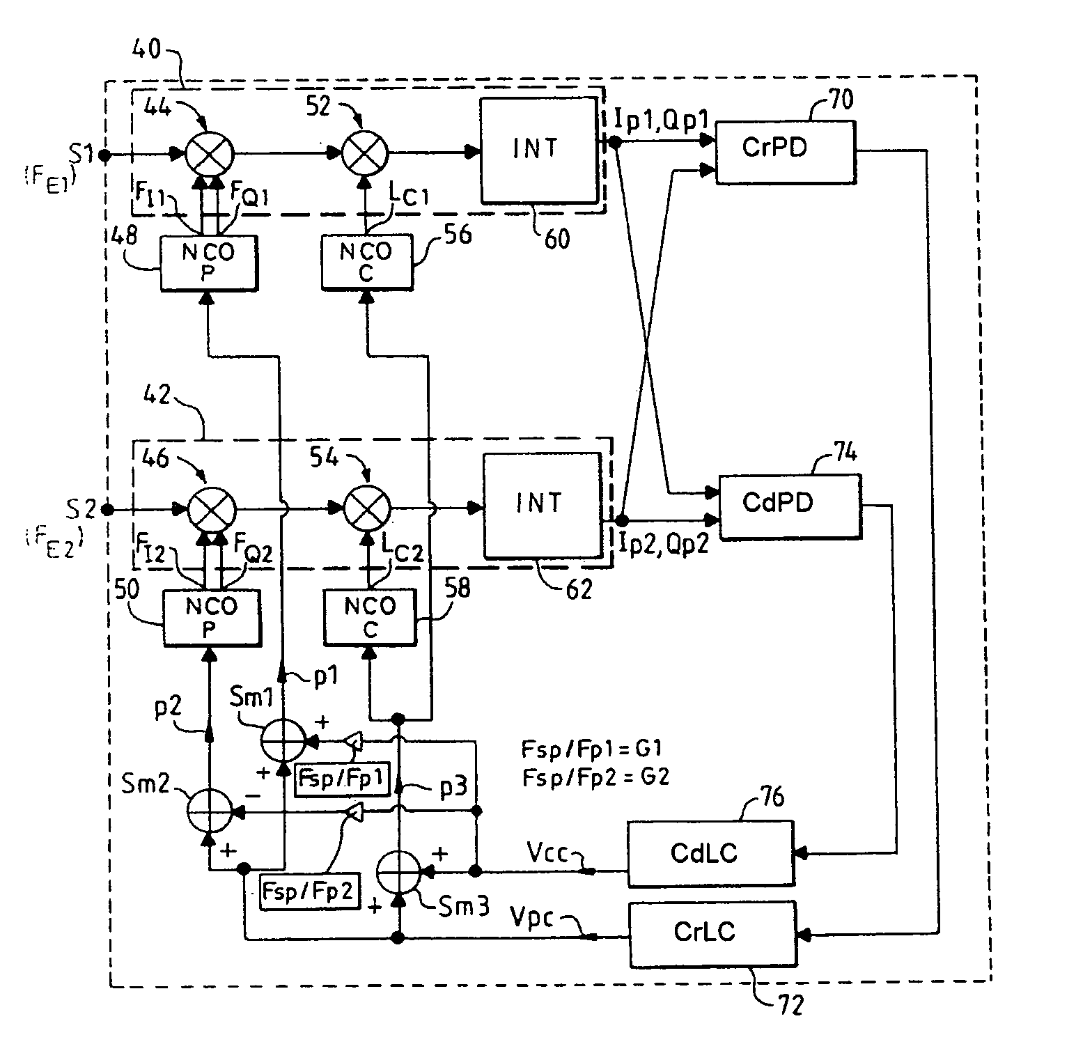
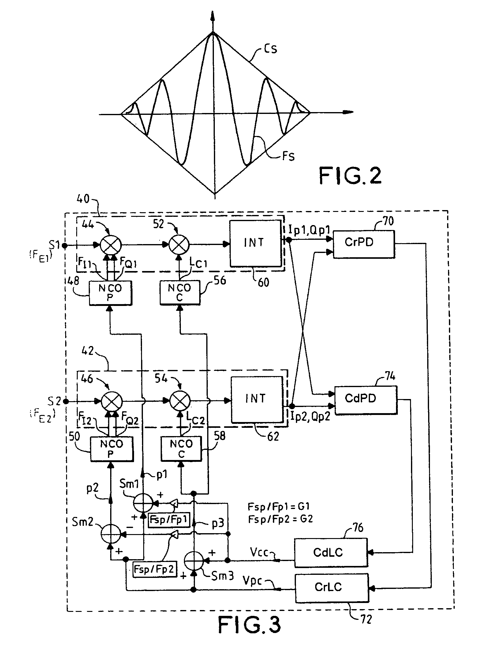
[0052]FIG. 3 shows a block diagram of a receiver according to the invention. In this embodiment shown in FIG. 3 the subcarrier loop or code loop is assisted by the central carrier loop.

[0053]The receiver shown in FIG. 3 includes a first correlator circuit 40 into which a first received signal S1 at a frequency FE1 is delivered and a second correlator circuit 42 into which the second received signal S2 at a frequency FE2 is delivered.

[0054]Each correlator circuit comprises a correlation channel 44, 46 for in-phase and quadrature correlation between its respective received signal S1, S2 and two respective local carriers FI1, FQ1 in the case of the first correlation channel 44 and FI2, FQ2 in the case of the second correlation channel 46, these local quadrature carriers being generated by a respective carrier numerically controlled oscillator 48, 50.

[0055]The signals I1, Q1 and I2, Q2 output by the carrier phase correlation channels are then correlated in a respective code correlation ...


PUM


Abstract

The invention relates to a satellite position pinpointing receiver intended to carry out combined processing of a first received radio signal and a second received radio signal which differ in frequency. The receiver comprises: a first correlator circuit and a second correlator circuit receiving the first and second received signals respectively, each correlator having a carrier correlation channel, a code correlation channel and a code correlation channel integrator. The receiver furthermore includes: a central-carrier phase discriminator; a device, the respective local carriers for the carrier correlation channels, a code phase discriminator; and a numerically controlled oscillator, for each correlation channel. Applications: satellite radio navigation by GPS, Galileo, Glonass, etc.

Description

CROSS-REFERENCE TO RELATED APPLICATIONS[0001]The present Application is based on International Application No. PCT / FR2003 / 001802, filed on Jun. 13, 2003, which in turn corresponds to FR 02 / 07377 filed on Jun. 14, 2002, and priority is hereby claimed under 35 USC §119 based on these applications. Each of these applications are hereby incorporated by reference in their entirety into the present application.FIELD OF THE INVENTION[0002]Satellite positioning systems employ, for pinpointing, several satellites that transmit their positions via radio signals and a receiver placed at the position to be pinpointed, estimating the distances, called pseudo-distances, that separate it from the satellites on the basis of the propagation times of the satellite signals picked up and performing the pinpointing operation by triangulation. The more precisely the satellite positions are known by the receiver and the more precise the measurements of the pseudo-distances made by the receiver are, the mo...

Claims


Application Information

Patent Timeline
Patent Type & Authority Patents(United States)
IPC IPC(8): G01S5/00G01S1/00G01S19/29G01S19/30G01S19/32
CPCG01S19/29G01S19/32G01S19/30
Inventor MARTIN, NICOLASREVOL, MARC
Owner THALES SA
Why Eureka
Try Eureka