Fault detection logic for engines

a technology of fault detection logic and engine control system, which is applied in the direction of machines/engines, analogue processes for specific applications, instruments, etc., can solve the problems of catastrophic consequences, unfavorable fault detection logic, and inability to detect the resultant variations in fuel flow, so as to avoid erroneous fault detection

Inactive Publication Date: 2007-02-27
ROLLS ROYCE DEUT LTD & CO KG
View PDF19 Cites 5 Cited by
  • Summary
  • Abstract
  • Description
  • Claims
  • Application Information

AI Technical Summary

Benefits of technology

[0007]The present invention, in a broad aspect, provides a fault detection logic for a control system of an engine which safely recognizes any loss of thrust control.
[0009]Accordingly, in the method of the present invention, a first control parameter with negative or positive sign corresponding to acceleration or deceleration is initially determined from which the respective control of thrust is then inferred. Since this statement does not make allowance for engine defects, for example in connection with the power supply of the fuel metering valve, and a loss of thrust control resulting therefrom is not recognized, a second thrust-dependent positive or negative control parameter is determined and established. If a logic query establishes that the parameter values determined transgress at the same time the respective specified threshold value, a hang in positive or negative acceleration determined by the second control parameter, with simultaneous, definite departure of the commanded engine pressure ratio from the actual engine pressure ratio, is a clear indication of a loss of thrust control and triggers a change-over to a second lane of the redundant system and / or an alarm signal. As a first control parameter, the difference between the command value and the actual value of the engine pressure ratio is used which, according to an intended acceleration or deceleration, is either positive or negative. As a second control parameter, the positive or negative acceleration of an engine shaft can be applied. This method ensures that a loss of thrust control is indicated. The method avoids erroneous fault detection by signal noise and, in addition, provides measures against false indications of loss of thrust control caused by engine surge.

Problems solved by technology

In certain cases—for example if voltage conditions in the solenoid system of the fuel metering unit are affected by power supply deficiencies resulting from defects in connecting leads, connectors or similar items—the fault detection logic will not be able to sense the resultant variations in fuel flow.
This inability manifests itself in a departure of the actual value of thrust and engine pressure ratio from the specified command value which is not recognized as fault by the fault detection logic.
If an engine fails to respond as a result of such a control behavior, i.e. a loss of thrust control without reaction of the engine controller or without indication of the malfunction, catastrophic consequences may occur.
Undetected excessive thrust of one of the two engines is also critical shortly before touchdown, in particular, since the thrust asymmetry resulting therefrom may cause the aircraft to leave the runway.
Since the fault detection system does not recognize this fault, catastrophic consequences as those described above may occur.
Generally, a loss of thrust control may occur throughout the flight, however, the consequences can be more serious in the above situations than, for example, at great altitude.

Method used


Image

  • Fault detection logic for engines
  • Fault detection logic for engines
  • Fault detection logic for engines

Examples


Embodiment Construction

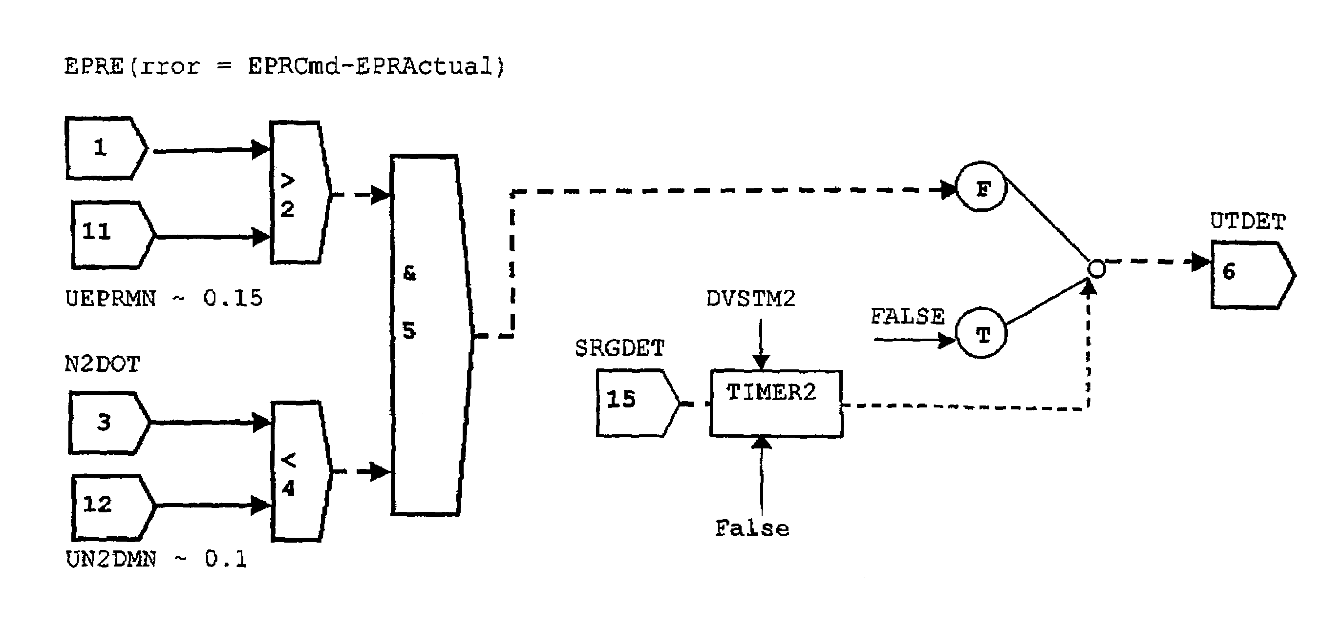
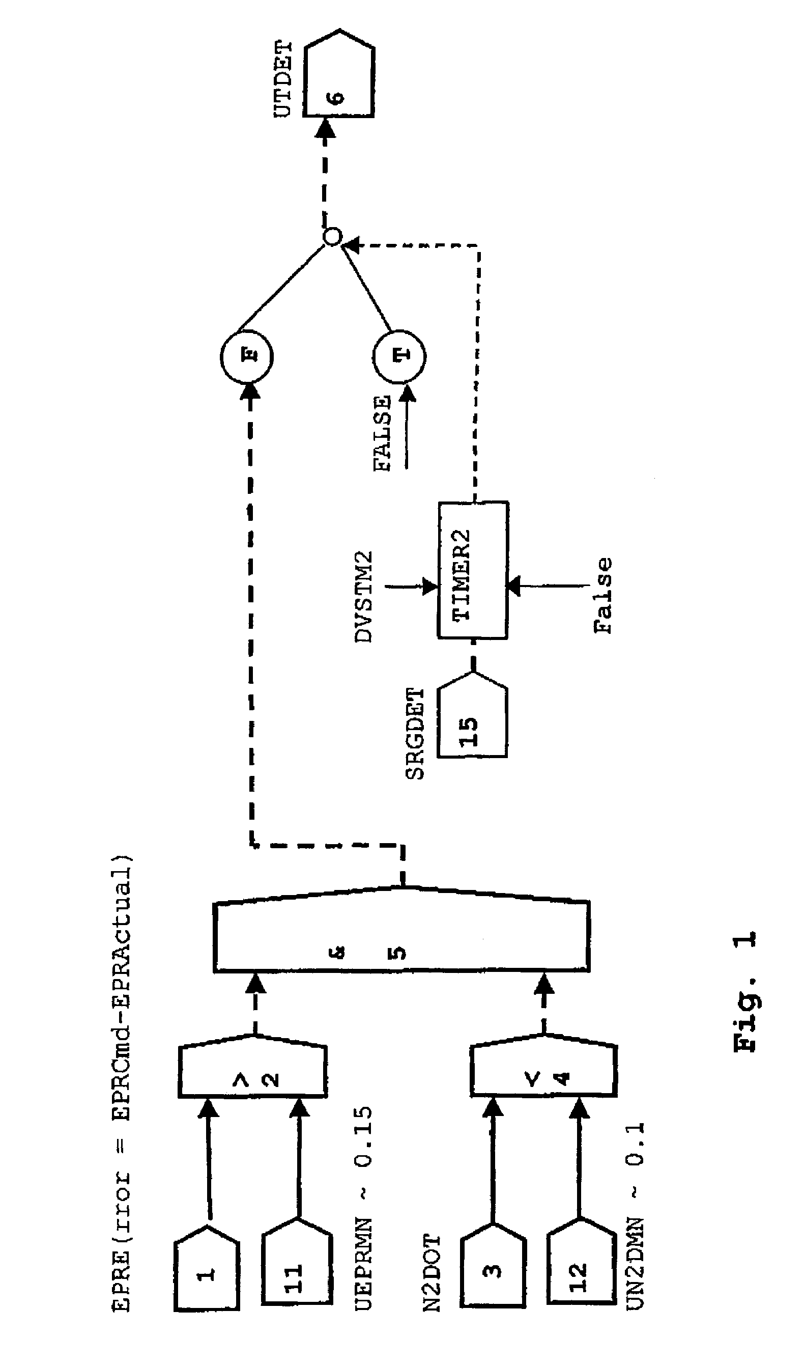
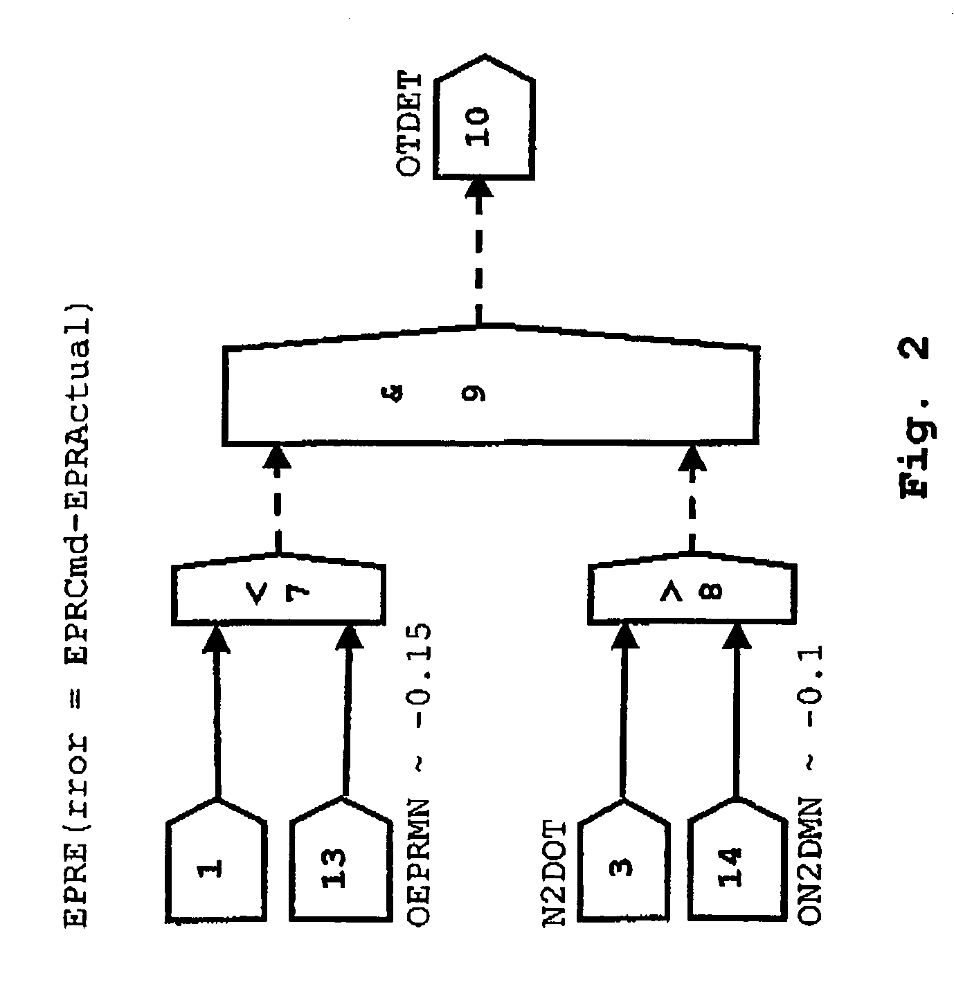
[0013]The term “underthrust” as used herein designates a lower thrust than that commanded by the pilot via the thrust lever setting, while the term “overthrust” conversely refers to a higher thrust than that commanded. Overthrust and underthrust are caused by a fault in the control system and denote a loss of thrust control (LOTC) which must be recognized and indicated and to which the control system must respond appropriately.

[0014]As shown in FIG. 1 and FIG. 2, the difference + / −EPRerror between the command value and the actual value is determined in step 1 as the first control parameter from the actual value of the engine pressure ratio (EPRactual) between the outlet and the inlet of the engine as a measure of the thrust and from the set command value of the engine pressure ratio (EPRcmd) as a measure of the demanded thrust. If the difference is positive, more fuel will be delivered via a fuel-metering unit (not shown) to the engine combustion chamber and the engine will be accel...


PUM


Abstract

In a fault detection logic for an engine controller for the detection of too low or too high a thrust relative to an intended positive or negative acceleration, the positive or negative error of the engine pressure ratio and the positive or negative acceleration of an engine shaft are simultaneously compared with a specified threshold, with the simultaneously determined transgression of both thresholds safely identifying a loss of thrust control. Disturbances caused by engine surge or signal noise are eliminated.

Description

[0001]This application claims priority to German Patent Application DE10302074.8 filed Jan. 21, 2003, the entirety of which is incorporated by reference herein.BACKGROUND OF THE INVENTION[0002]This invention relates to a fault detection logic for an engine control system to discover any loss of thrust control of the control loop.[0003]The control of engine thrust—and thus the control of the fuel flow required for the respective thrust—is effected in a known control system on the basis of the pressures measured at the inlet and at the outlet of the engine as the primary control parameter and the engine pressure ratio established therefrom. A positive difference between the command value and the actual value of the pressure ratio indicates an intended acceleration of the engine and, thus, an increase in fuel supply, while a negative value of the difference between the command value and the actual value of the engine pressure ratio signifies an intended deceleration of the engine and a...

Claims


Application Information

Patent Timeline
Patent Type & Authority Patents(United States)
IPC IPC(8): G01M17/00F02C9/26F02C9/28
CPCF02C9/263F02C9/28F05D2270/04F05D2270/051F05D2270/05
Inventor MANGELSDORF, TORSTEN
Owner ROLLS ROYCE DEUT LTD & CO KG
Why Eureka
Try Eureka