Utility knife with dual blades

a utility knife and dual blade technology, applied in the field of knives, can solve the problems of user injury, user pulling a utility knife toward the user, and dangerous situations

Inactive Publication Date: 2007-03-06
AWI ACQUISITION
View PDF9 Cites 46 Cited by
  • Summary
  • Abstract
  • Description
  • Claims
  • Application Information

AI Technical Summary

Benefits of technology

[0009]A first basic embodiment of the present invention is directed to a utility knife which has a dome-shaped housing having a top portion, two side portions, a front portion, a rear portion and an internal chamber. The housing has a footplate and the footplate has a fore end and an aft end. A first slot and a second slot are formed in the footplate with the first slot located directly adjacent the fore end and the second slot located directly adjacent the aft end. Both the first and second slots are located along the longitudinal middle of the footplate of the housing. The footplate is then able to be adapted to be placed against a workpiece that is to be cut. A blade holder is mounted within the internal chamber that is capable of housing a plurality of blades. The blade holder is pivotable relative to the housing between a fore position and an aft position. A first blade and a second blade are mounted ...

Problems solved by technology

Pulling of a utility knife toward the user can, in some instances, be a dangerous situation.
If the knife slips or becomes free of the workpiece, the knife can actually be pulled by the user directly into the user's body causing injury to the user.
Also, if performing of cuts on a ...

Method used


Image

  • Utility knife with dual blades
  • Utility knife with dual blades
  • Utility knife with dual blades

Examples


Embodiment Construction

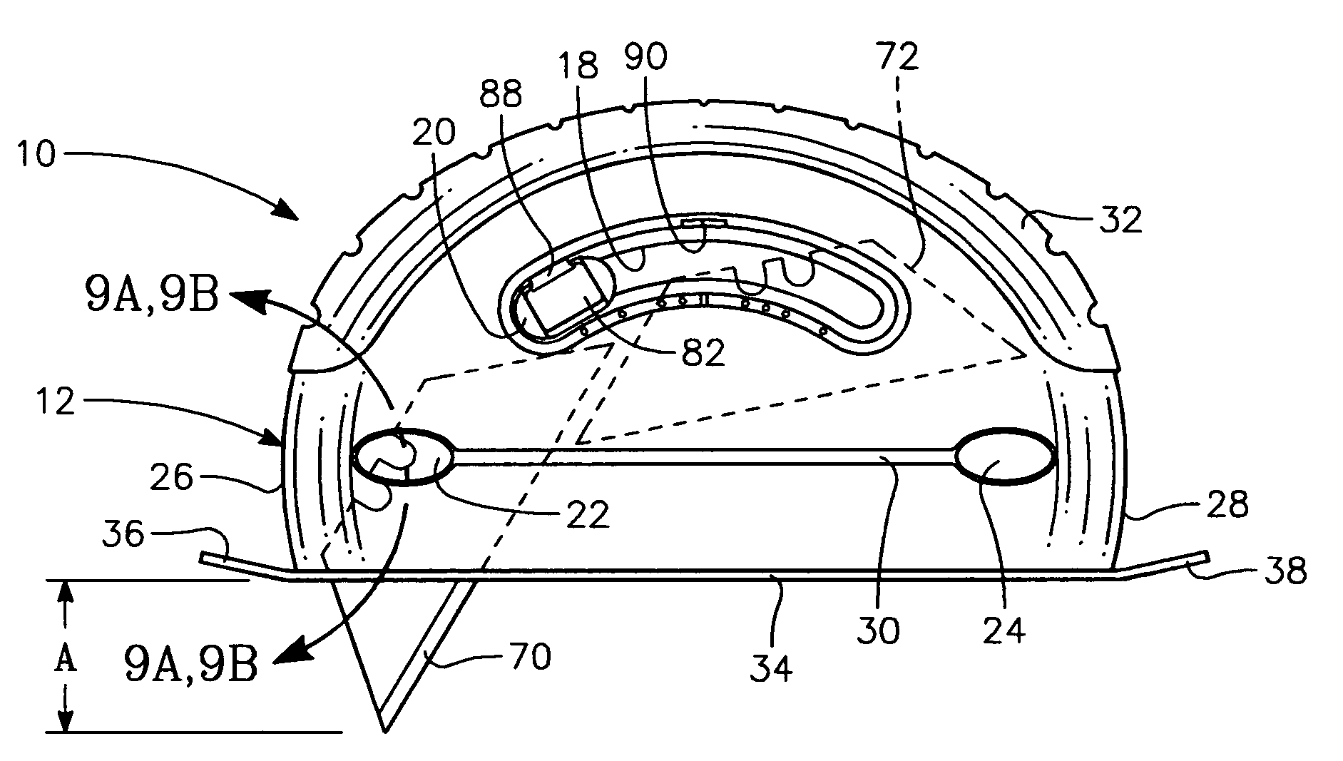
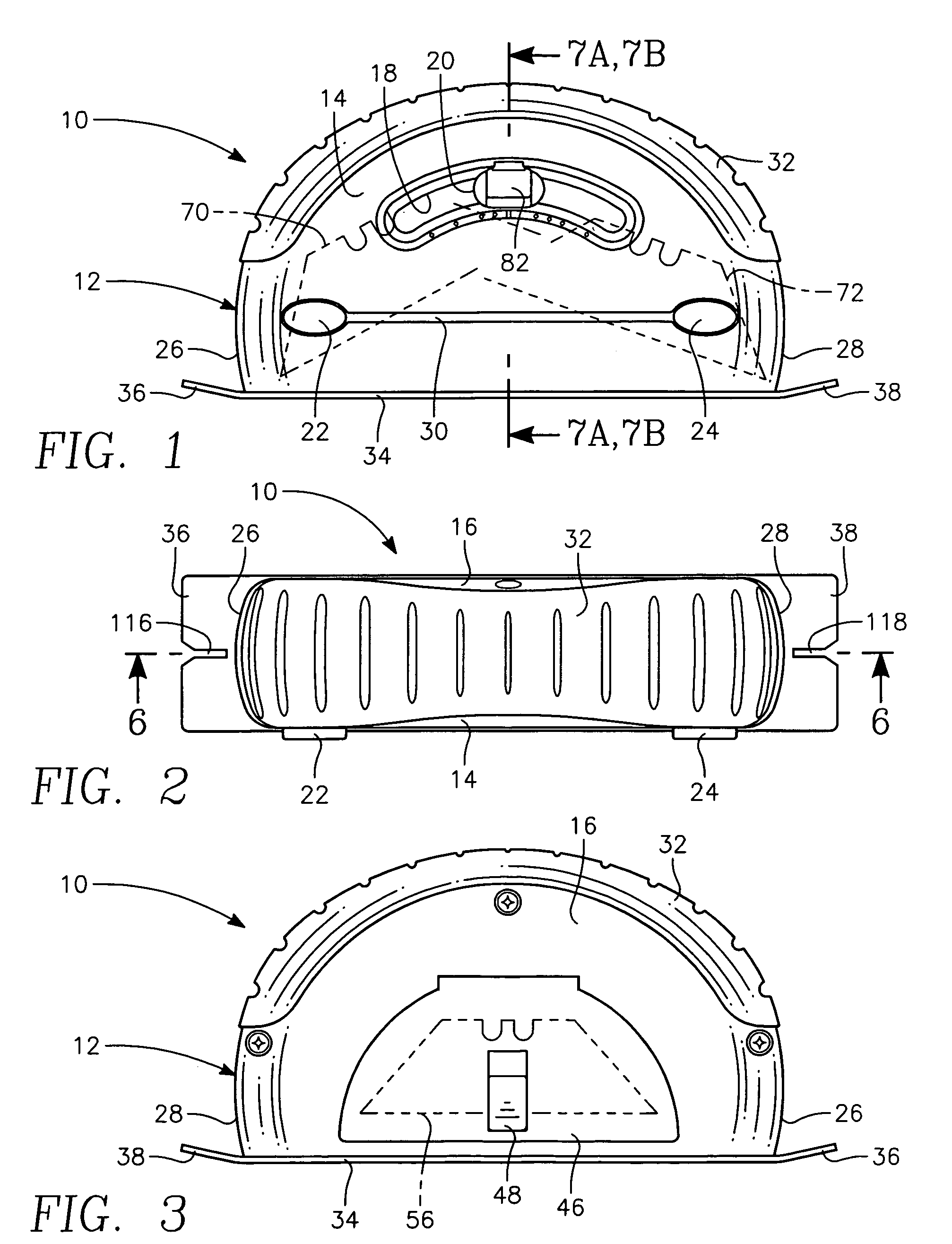
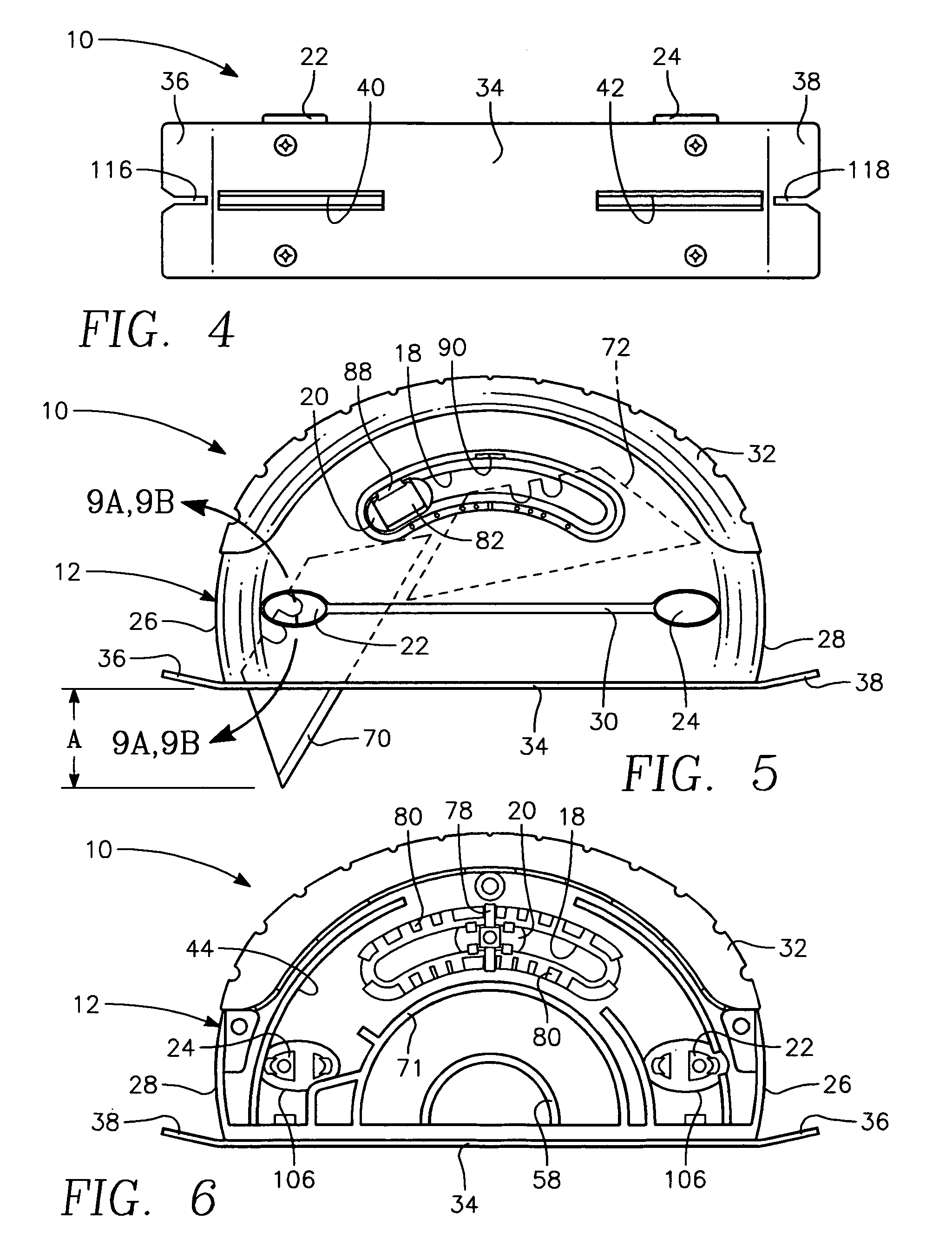
[0036]Referring particularly to the drawings, there is shown in FIGS. 1–4 the exterior of the utility knife 10 of this invention. The utility knife 10 has a dome-shaped housing 12 which has a front side 14 and a rear side 16. The front side 14 includes an arcuate slot 18. Mounted within the arcuate slot 18 is a slidable button 20. Also mounted within the front side 14 are a pair of spaced apart push buttons 22 and 24. The operation and construction of push buttons 22 and 24 are basically identical. The push button 22 is located directly adjacent the fore end 26 of the housing 12 and push button 24 is located directly adjacent the aft end 28 of the housing 12. Interconnecting the push buttons 22 and 24 is a longitudinal groove 30. The function of the groove 30 is strictly for ornamentation.

[0037]The dome shape of the housing 12 is to be covered with a resilient material, such as a rubber or rubberized plastic 32. The palm area of the user's hand is to be in contact with the rubber la...


PUM

PropertyMeasurementUnit
Timeaaaaaaaaaa

Abstract

A utility knife that includes a pair of blades mounted on a blade holder. One blade is to be extendable from the housing of the utility knife adjacent the fore end of the utility knife with the other blade to be extendable from the housing to be usable for adjacent the aft end of the housing. The blade at the fore end of the housing is to be usable by the user exerting a pulling action toward the user with the blade at the aft end of the housing to be usable by the user exerting a pushing action against the housing.

Description

BACKGROUND OF THE INVENTION[0001]1. Field of the Invention[0002]The field of this invention relates to knifes and more particularly to a utility knife that is commonly used by homeowners and building trade individuals.[0003]2. Description of the Related Art[0004]Utility knives have long been known. A typical utility knife has an elongated body with there being a slot located within the fore end of the elongated body. There is a slidable button mounted on the housing and the user is to move the slidable button to cause a blade to be extended from the body. The utility knife is then to be used in a motion pulling the knife across a workpiece in the direction of the user to perform a cut.[0005]People in the building trade business, such as contractors and carpenters, utilize utility knives frequently. Pulling of a utility knife toward the user can, in some instances, be a dangerous situation. If the knife slips or becomes free of the workpiece, the knife can actually be pulled by the u...

Claims


Application Information

Patent Timeline
IPC IPC(8): B26B3/06B26B29/02
CPCB26B27/005B26B5/001Y10T83/8769
Inventor TSENG, YI CHUAN
Owner AWI ACQUISITION
Why Eureka
Try Eureka