Ultralight coaxial rotor aircraft

Inactive Publication Date: 2007-04-03
AEROTWIN MOTORS
View PDF54 Cites 80 Cited by
  • Summary
  • Abstract
  • Description
  • Claims
  • Application Information

AI Technical Summary

Benefits of technology

[0022]In another more detailed aspect, the control system can be configured to keep the pilot aware of altitude and to keep the forward speed of the aircraft below a threshold value, so that the aircraft stays low to the ground and relatively slow in relative speed to mitigate harm to the operator from a crash. Furthermore, an emergency power system can be provided to provide temporary power to the rotors for landing in the event of sudden loss of engine power. This system can be powered by stored compressed air, or by another gas generated rapidly from a chemical gas g

Problems solved by technology

Without the tail rotor to provide the counter-moment, the airframe could rotate uncontrollably once airborne due to these reaction forces.
While, as mentioned, coaxial helicopters have been known for many years, development of this type of aircraft has heretofore been limited because of complexities involved in arrangements for control of the rotor blades to give roll, pitch and yaw control.
The control arrangements are necessarily complex, and relatively high forces must be transferred by the swashplate assemblies and control links, so they must be robust, and accordingly, heavy.
This arrangement does not allow differential co

Method used


Image

  • Ultralight coaxial rotor aircraft
  • Ultralight coaxial rotor aircraft
  • Ultralight coaxial rotor aircraft

Examples


Embodiment Construction

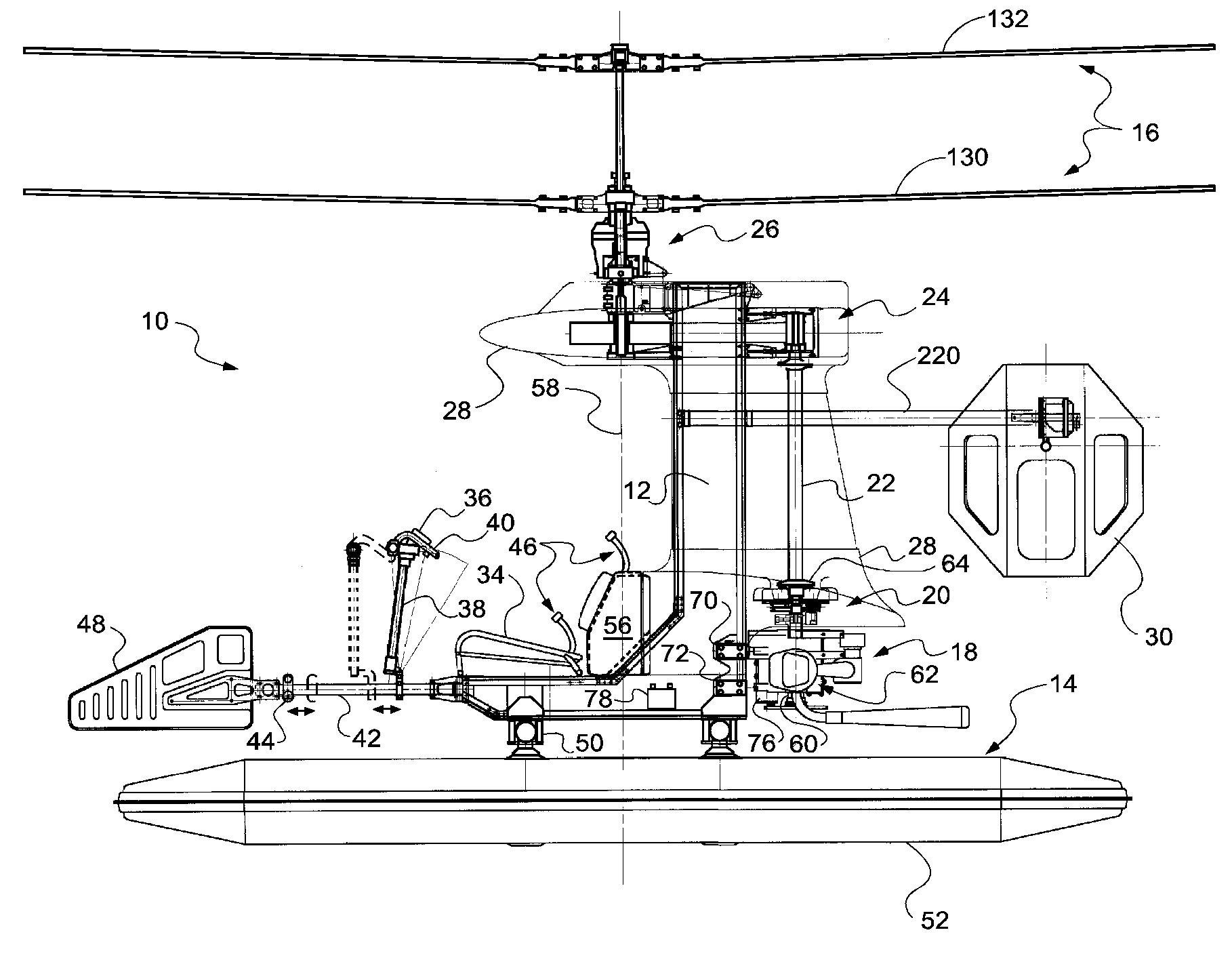
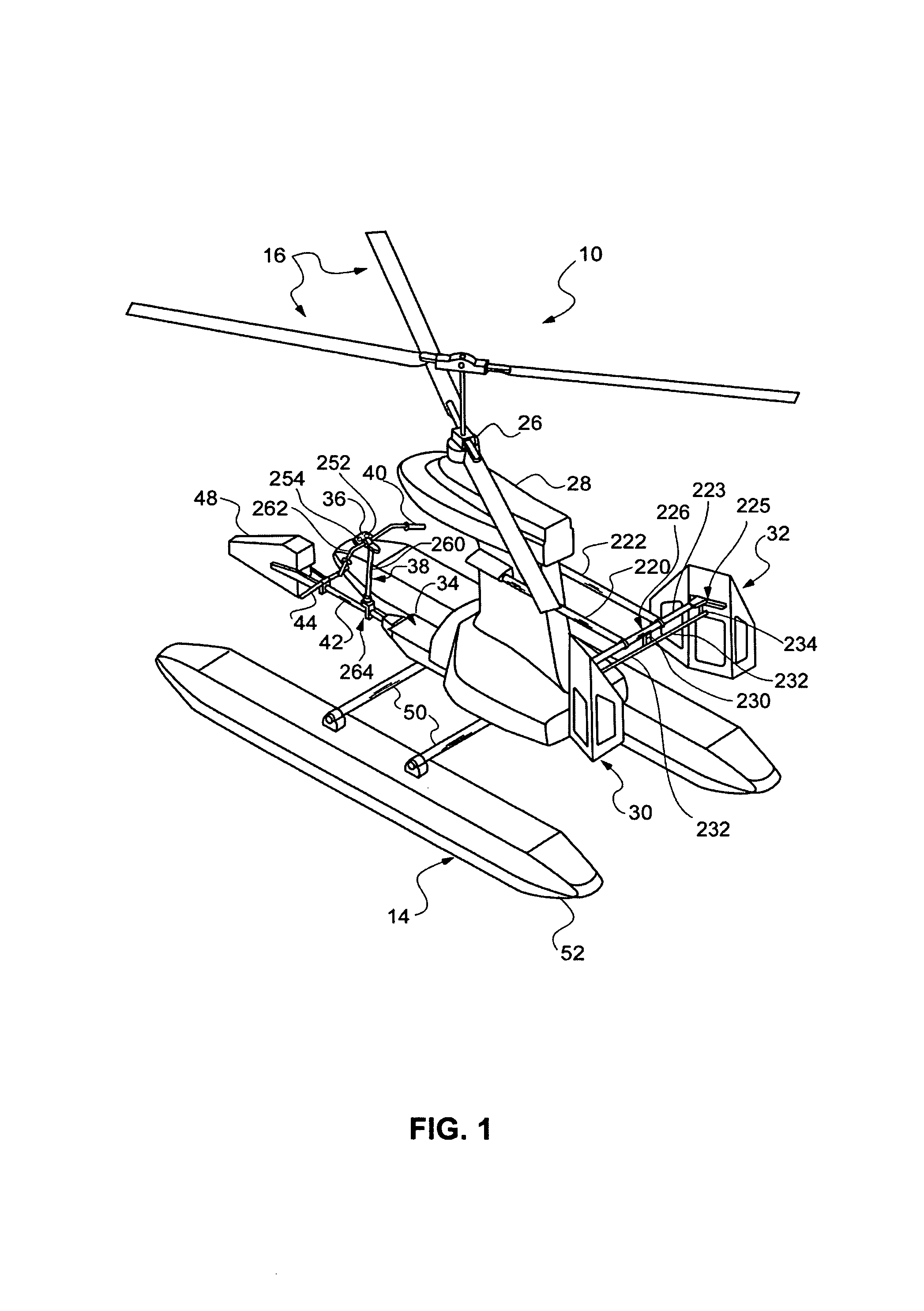
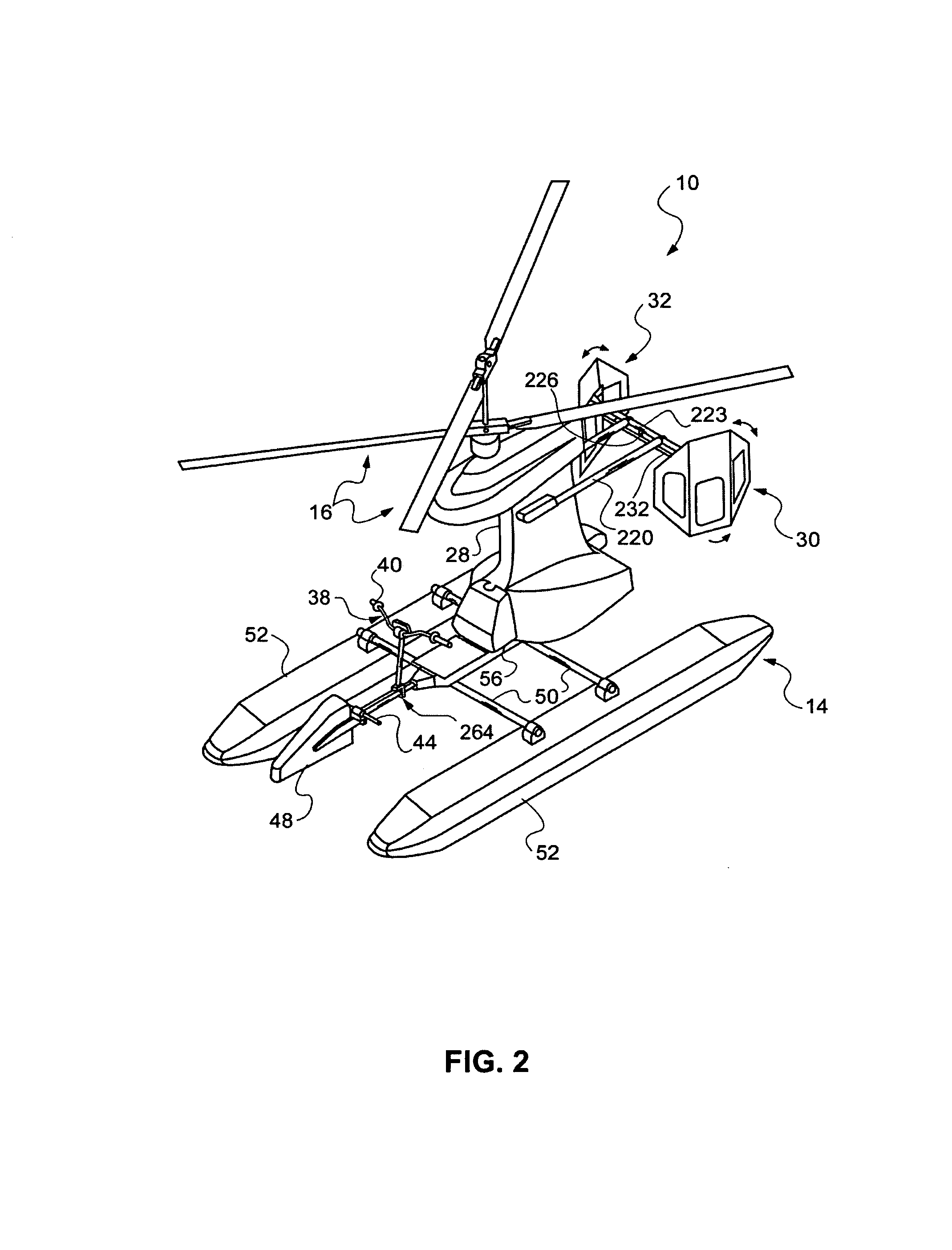
[0042]Reference will now be made to the drawings in connection with the following detailed description, in which the various elements of the illustrated example(s) of embodiments of the invention will be described and discussed. It is to be understood that the following description is only exemplary of the principles of the present invention, and should not be viewed as limiting of the scope of the invention.

[0043]With reference to FIGS. 1 through 6 of the drawings, the invention is embodied in an ultralight helicopter 10 having a generally L shaped airframe 12 supported by pontoon landing skids 14 while on the ground, and a coaxial rotor set 16 when airborne. A gasoline engine 18 powers the coaxial rotors through a centrifugal and sprag clutch unit 20, drive shaft 22, belt drive transmission 24, and rotor coaxial drive transmission gear box 26. The engine, clutch, drive shaft, and belt drive transmission can be enclosed, either partly or entirely, within a sleek aerodynamic cowling...


PUM


Abstract

An ultralight coaxial dual rotor helicopter having a substantially L shaped frame. Attached to the back of the frame is a vertical shaft engine, and a pair of yaw paddles for controlling yaw of the craft. The drive shaft connects to a belt drive at the top of the frame, which transmits the engine power to a transmission and coaxial drive gear for driving the rotors. Crank actuators are provided for tilting the rotor axis to control the pitch and roll of the craft. A pilot seat and ballast tank are attached to the front of the frame. The ballast tank may be filled with a volume of water to balance the craft for the weight of the pilot. The fuel tank is located behind the pilot seat on the centerline of the helicopter, such that as fuel is used and the weight of fuel in the tank changes, the balance of the craft will not be affected.

Description

[0001]This application claims priority of U.S. provisional application Ser. No. 60 / 268,978, filed Feb. 14, 2001, which is hereby incorporated herein by reference for the teachings consistent herewith, and this disclosure shall control in case of any inconsistency.BACKGROUND OF THE INVENTION[0002]1. Field of the Invention[0003]This invention relates to coaxial helicopter systems. More particularly, the present invention relates to an ultralight coaxial helicopter system.[0004]2. Discussion of the Related Art[0005]Coaxial helicopters were first developed, in the form of small devices used as toys and curiosities, centuries ago. The earliest attempts at designing a practical helicopter focused on coaxial rotors and dual counter-rotating arrangements. Later, what has come to be thought of as conventional helicopter designs were developed. These were single-rotor helicopters, and it was found that they needed a long tail boom having a tail rotor at the end rotating in a plane roughly per...

Claims


Application Information

Patent Timeline
IPC IPC(8): B64C27/10B64C27/52B64C31/028
CPCB64C27/10B64C27/52B64C31/028
Inventor PHELPS, III, ARTHUR E.BARNES, DWAINE R.NORRIS, ELWOOD G.ROCK, EUGENE F.WALLACE, EMITT
Owner AEROTWIN MOTORS
Why Eureka
Try Eureka