Image heating apparatus

a heating apparatus and image technology, applied in the field of image heating apparatus, can solve the problem of not being able to confine the steam generated

Active Publication Date: 2007-04-03
CANON KK
View PDF6 Cites 51 Cited by
  • Summary
  • Abstract
  • Description
  • Claims
  • Application Information

AI Technical Summary

Benefits of technology

[0008]The primary object of the present invention is to provide an image heating apparatus which is structured to form a nip with the use of first and second belts, and which does not suffer from the problem that an image is unsatisfactorily heated.

Problems solved by technology

However, the fixing apparatus disclosed in Japanese Laid-open Patent application 2004-341346 suffers from the following problems.
On the other hand, the portion of the fixation nip, which has virtually no pressure, fails to confine the steam which generates as heat is applied.

Method used


Image

  • Image heating apparatus
  • Image heating apparatus
  • Image heating apparatus

Examples


embodiment 1

[0018]First, referring to FIG. 6, the general structure of a typical image forming apparatus will be described.

[0019]The image forming apparatus shown in FIG. 6 is an image forming apparatus (so-called printer) which employs an electrophotographic image forming method.

[0020]The image forming apparatus 1 can be roughly divided into an image forming means for forming a toner image on a sheet of recording medium, and a fixing apparatus, as an image heating apparatus, for fixing the toner image formed on the sheet of recording medium, by applying heat and pressure to the toner image.

[0021]The image forming means is equipped with a photosensitive drum 2 as an image bearing member, a charging device 3 as a charging means, an exposing apparatus as an exposing means, a developing device 6 as a developing means, a recording medium feeder cassette 9; a feeding-and-conveying roller 10, a pair of registration rollers 11, a transfer roller 7 as a transferring means, and a cleaning apparatus 8 as...

embodiment 2

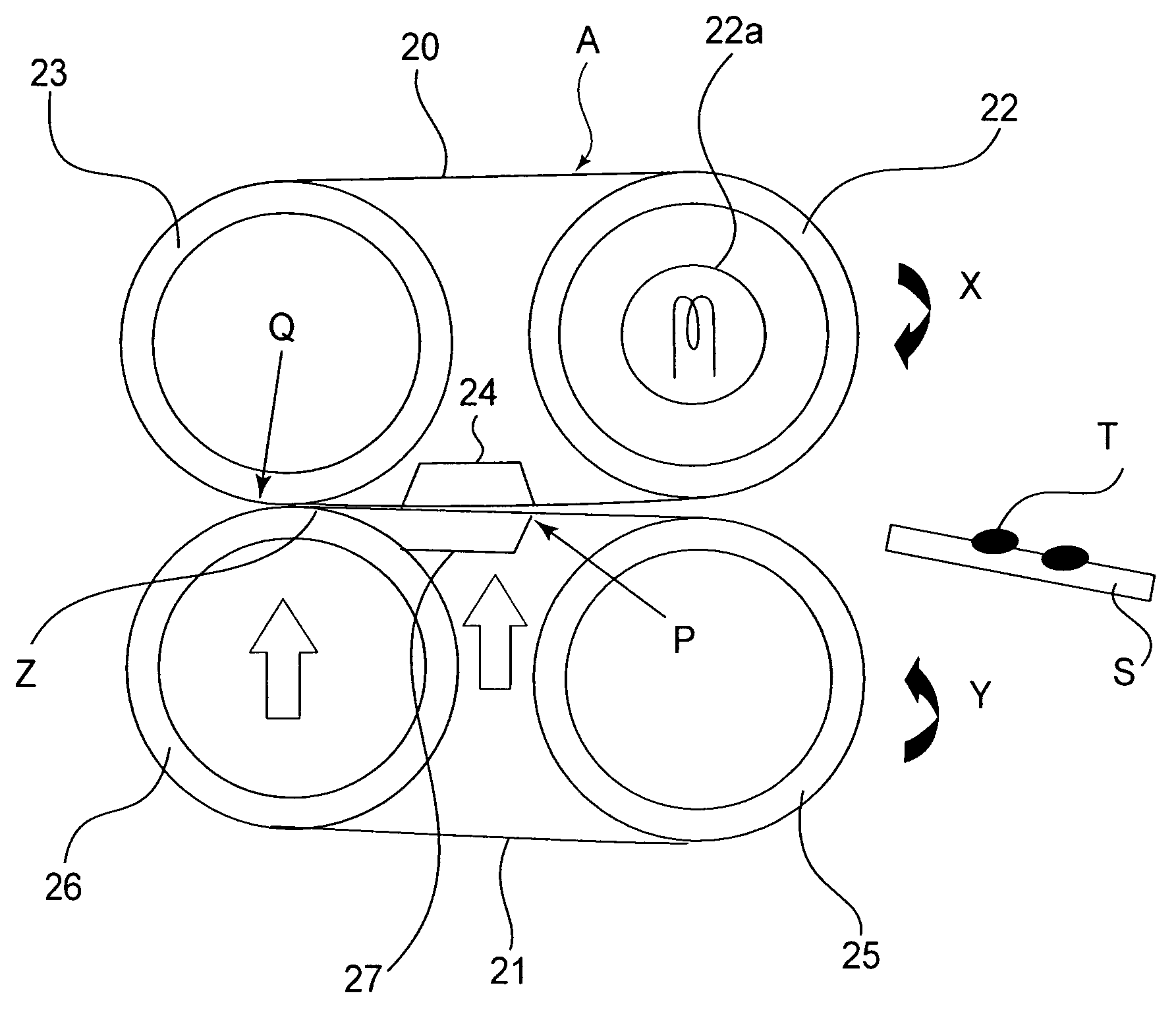
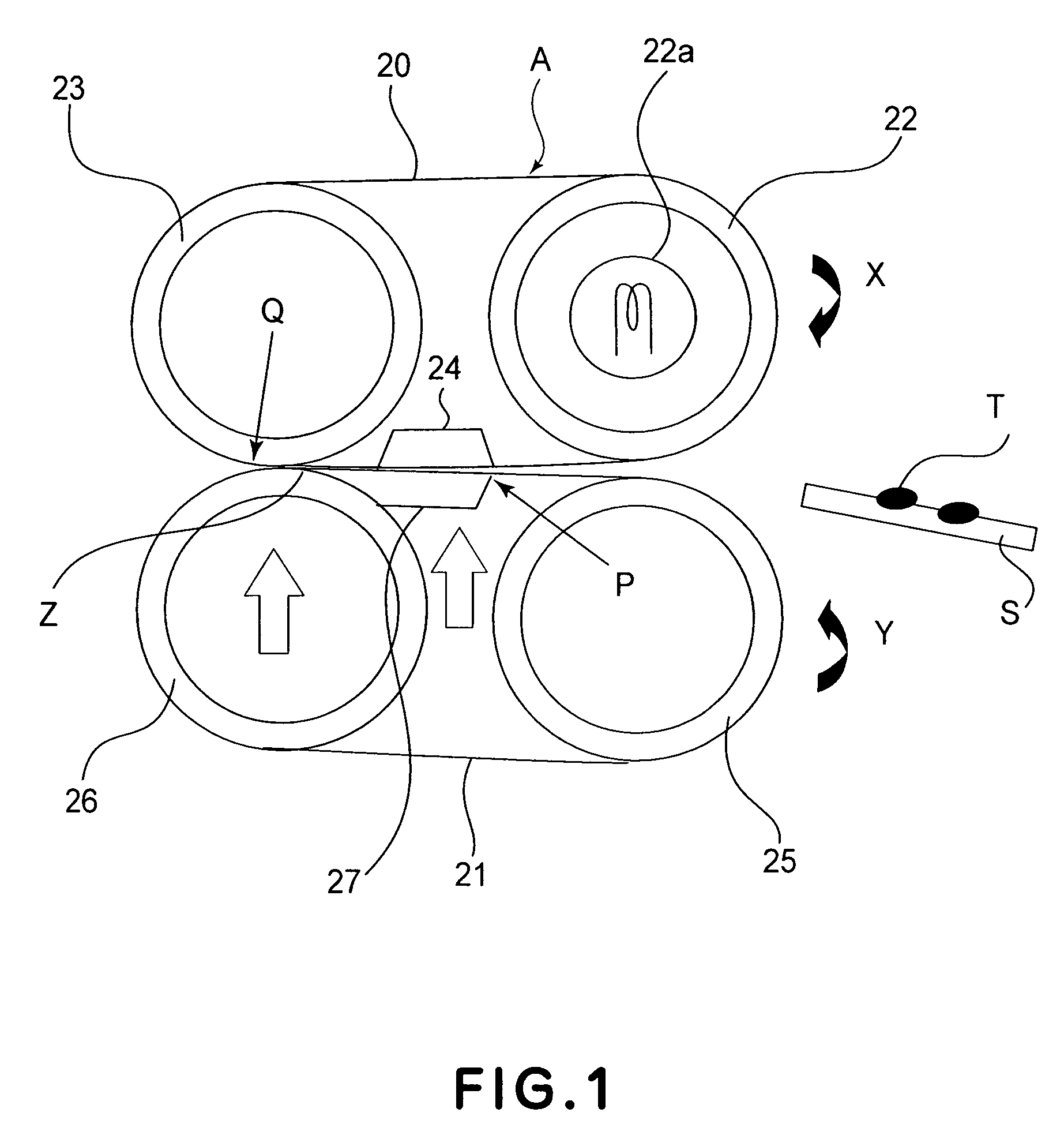
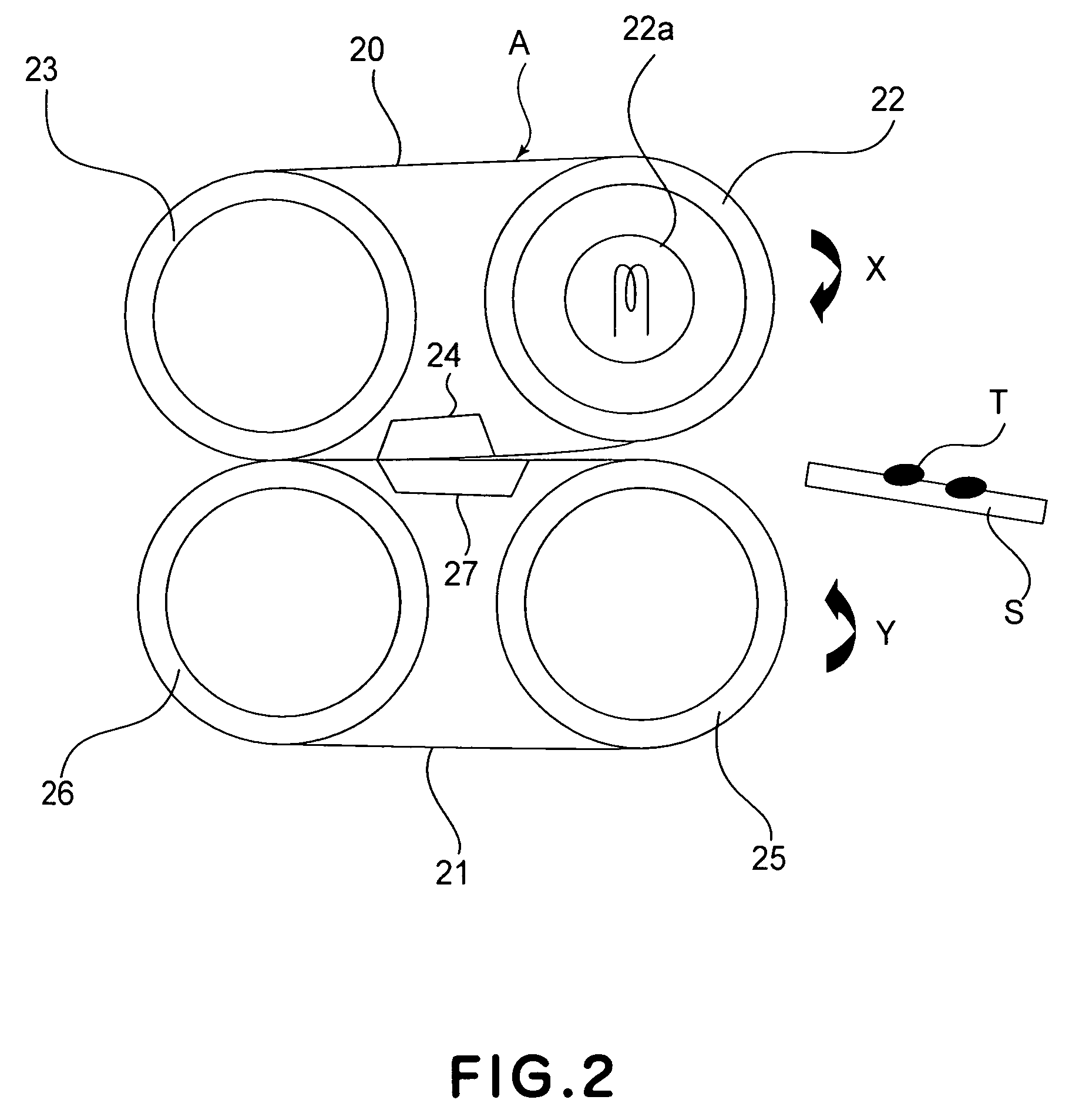
[0068]Next, the fixing apparatus and image forming apparatus in the second embodiment of the present invention will be described. The sectional views of these apparatuses are the same as those for the first embodiment. Therefore, the apparatuses will be described with reference to FIG. 1.

[0069]The fixation pad 24 in this embodiment is formed of a resin, more specifically, PPS (polyphenyl sulphide resin). However, the material for the fixation pad 24 does not need to be limited to resin, as long as the resultant fixation pad 24 is rigid and is not provided with the elastic rubber layer. For example, it may be formed of a metallic substance. Otherwise, the structure of the fixing apparatus in this embodiment is the same as that in the first embodiment.

[0070]In the case of a fixing apparatus, such as the one in the first embodiment, which employs a fixation pad formed of rubber, there is the fear that as the fixation nip is formed (as pressure is applied), the elastic deformation of th...

embodiment 3

[0075]FIG. 5 is a drawing which simply shows the fixing apparatus in another embodiment of the present invention. The fixing apparatus in this embodiment is reverse to the fixing apparatus in the first embodiment, in terms of the structures of the fixation side and pressure application side.

[0076]More specifically, in this embodiment, a rigid roller is employed as the fixation roller 23, which is disposed within the loop of the fixation belt 20, and an elastic pad is employed as the fixation pad 24. Further, the fixation pad 24 is disposed in contact with the fixation roller 23.

[0077]Moreover, an elastic roller is employed as the pressure application roller 26 (which is given the function of receiving inputted driving force and transmitting it to pressure application belt), which is disposed within the loop of the pressure application belt 21, and a rigid pad is employed as the pressure application pad 27, which in this embodiment is disposed close to the pressure application roller...


PUM


Abstract

An image heating apparatus comprising first and second belts for forming a nip for heating an image on a recording material; a first pressing pad for pressing the first belt at the nip; a first roller, provided spaced from the first pressing pad with a gap therebetween, for pressing the first belt at the nip; a second pressing pad, provided opposed to the first pressing pad, for pressing the second belt at the nip; a second roller, provided opposed to the first roller and contacted to the second pressing pad, for pressing the second belt at the nip, the second roller having a friction coefficient which is smaller than that of the first roller.

Description

FIELD OF THE INVENTION AND RELATED ART[0001]The present invention relates to an image heating apparatus for heating an image formed on recording medium. Such an image heating apparatus is employed by a copying machine, a printing machine, a facsimile machine, etc.[0002]A fixing apparatus for an electrophotographic image forming apparatus fixes a toner image formed on a sheet of recording medium, to the sheet of recording medium, by applying pressure to the toner image while heating it. As one of various fixing apparatuses, there is a so-called roller-based fixing apparatus, which is made up of a fixation roller and a pressure application roller (which hereafter will be simply referred to as pressure roller). The fixation roller and pressure roller are pressed against each other to form a fixation nip. A roller-based fixing apparatus has long been used in the field of electrophotographic image forming apparatuses.[0003]For the purpose of raising the glossiness level at which an image...

Claims


Application Information

Patent Timeline
Patent Type & Authority Patents(United States)
IPC IPC(8): G03G15/20
CPCG03G15/206G03G2215/2022G03G15/2064G03G15/2053G03G2215/2009
Inventor NAKAMOTO, IKUOHAYASHI, YASUHIROMATSUURA, DAIGOHASEGAWA, KAZUHIROTAKADA, SHIGEAKI
Owner CANON KK
Why Eureka
Try Eureka