Vehicular headlamp with semiconductor light emitting elements and electric discharge bulb

a technology of semiconductor light emitting elements and electric discharge bulbs, which is applied in the direction of fixed installation, lighting and heating apparatus, lighting support devices, etc., can solve the problems of deteriorating a degree of freedom of design and affecting the appearance of the lamp piece. , to achieve the effect of improving the outlook of the lamp piece and preventing an unusual visual impression

Inactive Publication Date: 2007-04-10
KOITO MFG CO LTD
View PDF8 Cites 28 Cited by
  • Summary
  • Abstract
  • Description
  • Claims
  • Application Information

AI Technical Summary

Benefits of technology

[0013]The present invention has been carried out in view of such a situation. It is an object of the present invention to provide a vehicular headlamp capable of preventing an unusual visual impression from being given to a driver (or other person in the vehicle) when a beam is switched between a low beam and a high beam. It is another object of the present invention to achieve improvement of an outlook of a lamp piece when the lamp piece is lighted in a high beam mode in a vehicular headlamp, including a lamp piece unit constituting a light source by a semiconductor light-emitting element.

Problems solved by technology

However, when the semiconductor light-emitting element is used as the light source, an amount of irradiated light from the lamp piece unit cannot be ensured sufficiently.
As a result; there is a related art problem in that the number of the lamp piece units is considerably increased to result in deterioration in a degree of freedom of design of the lamp piece.
Therefore, the below-described related art problem occurs.
There is a related art problem of producing an unusual visual impression for a driver when the beam is switched from the low beam to the high beam.
Further, in the high beam mode simultaneously lighting the first and the second lamp piece units, there is also a related art problem in that an outlook of the lamp piece unit is deteriorated since a visual impression of unity in color between the two lamp piece units is not achieved.

Method used


Image

  • Vehicular headlamp with semiconductor light emitting elements and electric discharge bulb
  • Vehicular headlamp with semiconductor light emitting elements and electric discharge bulb
  • Vehicular headlamp with semiconductor light emitting elements and electric discharge bulb

Examples


Embodiment Construction

[0037]An embodiment of the invention will be explained in reference to the drawing as follows.

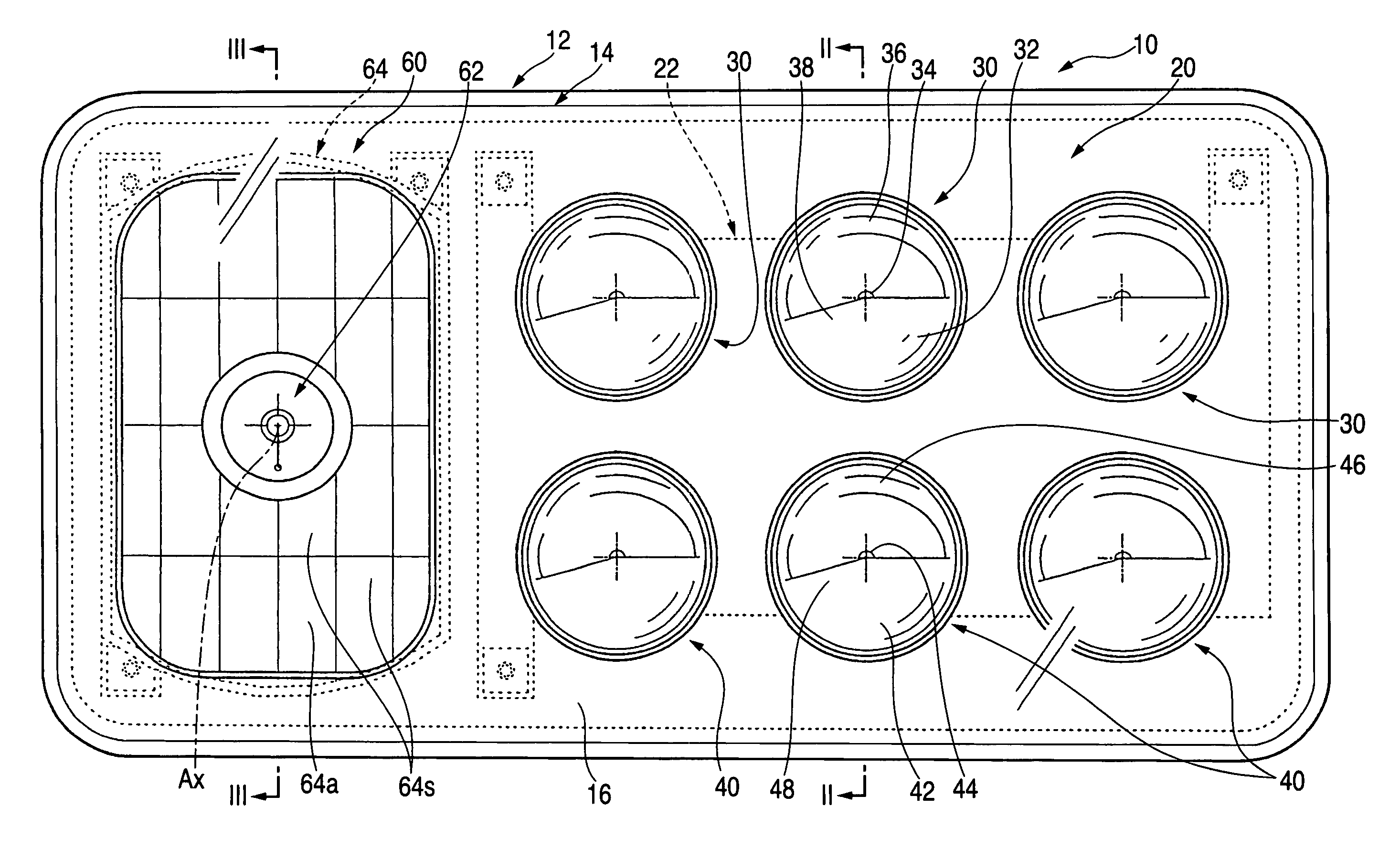
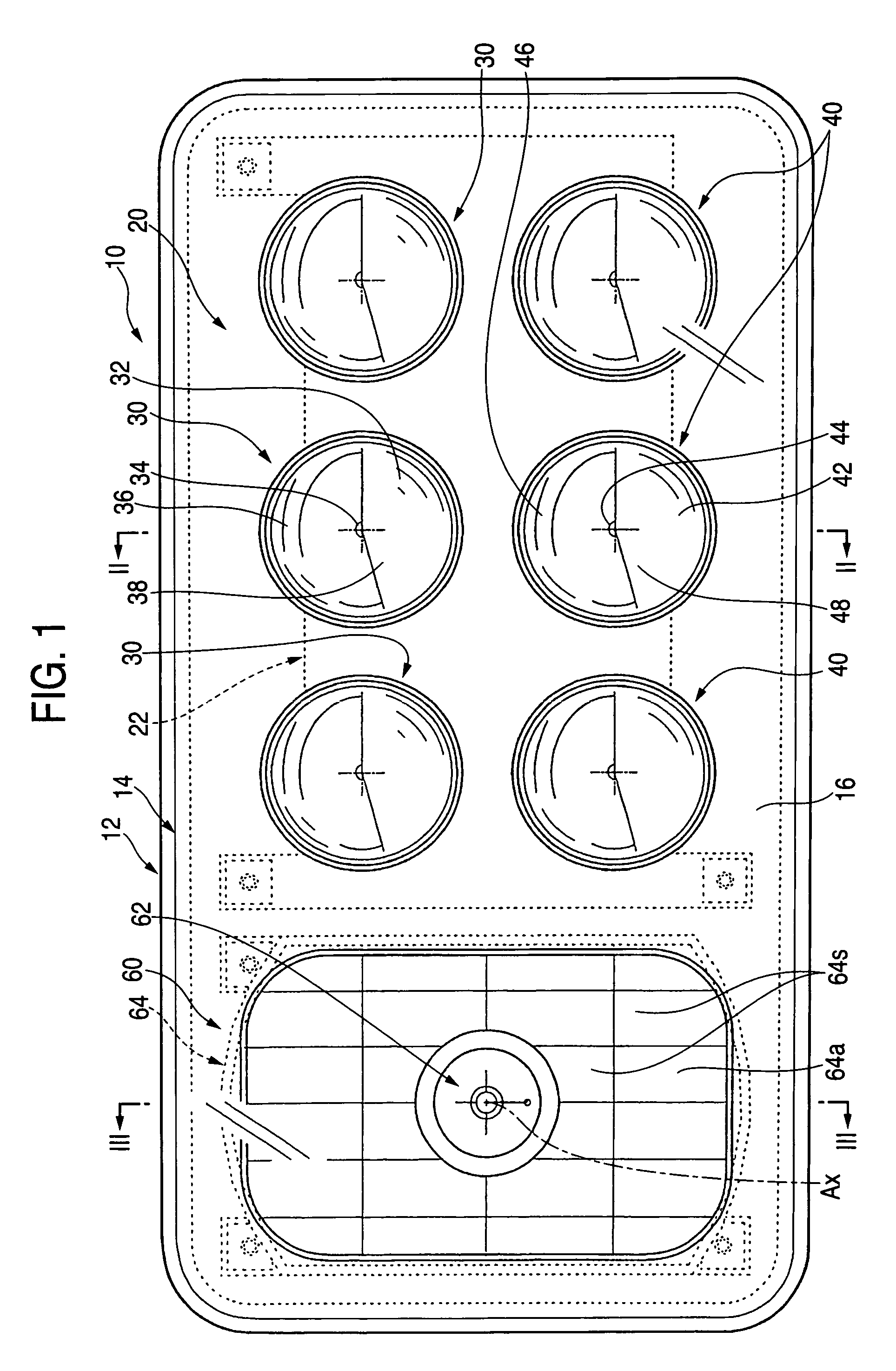
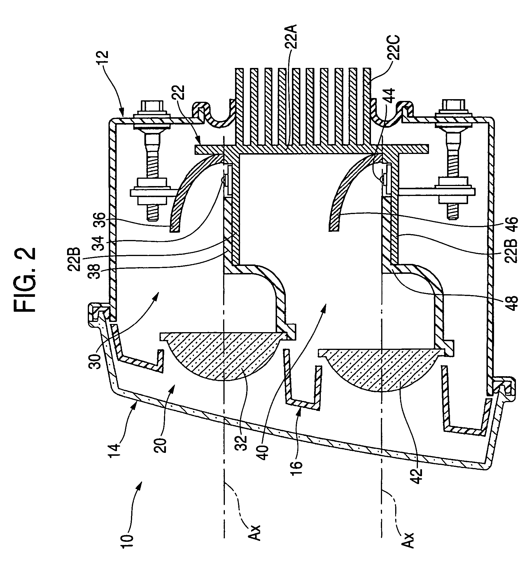
[0038]FIG. 1 is a front view showing a vehicular headlamp according to an exemplary, non-limiting embodiment of the present invention, and FIGS. 2 and 3 are a sectional view taken along a line II—II of FIG. 1 and a sectional view taken along a line III—III thereof, respectively.

[0039]A vehicular headlamp 10 is constituted such that a first lamp piece unit 20 and a second lamp piece unit 60 are contained inside a lamp chamber formed by a lamp body 12 and a transparent light transmitting cover 14 attached to an opening portion of a front end thereof, to be inclinable in an up and down direction and a left and right direction, respectively, via aiming mechanisms arranged contiguously to the left and to the right. Further, an inner panel 16 formed to surround the first and the second lamp piece units 20, 60 is provided along the light transmitting cover 14 inside the lamp chamber.

[0040]The vehi...


PUM


Abstract

A plurality of lamp piece units constituting light sources by semiconductor light emitting elements are used as a first lamp piece unit which is lighted in a low beam mode. Additionally, a single lamp piece unit constituting a light source by an electric discharge bulb color temperature of emitted light of which is as high as that of the semiconductor light emitting element, is used as a second lamp piece unit, which is additionally lighted in a high beam mode. When the beam is switched from the low beam to the high beam, pale irradiated light from the first lamp piece unit is added with pale irradiated light from the second lamp piece unit to thereby provide an impression for the driver and / or passenger of unity in colors between the two lamp piece units.

Description

[0001]The present application claims foreign priority based on Japanese Patent Application No. 2003-374059, filed Nov. 4, 2003, the contents of which is incorporated herein by reference.[0002]1. Field of the Invention[0003]The present invention relates to a vehicular headlamp including a lamp piece unit constituting a light source by a semiconductor light-emitting element.[0004]2. Background of the Invention[0005]In the related art, a vehicular headlamp is constituted to be able to switch a beam between a low beam and a high beam setting. More specifically, there is a related art vehicular headlamp constituted such that in a low beam mode a first lamp piece unit is lighted, and in a high beam mode the first lamp piece unit as well as a second lamp piece unit are simultaneously lighted.[0006]In such a vehicular headlamp, Japanese patent publication JP-A-2003-7104 describes a vehicular headlamp using an electric discharge bulb as a light source of the first lamp piece unit and a halog...

Claims


Application Information

Patent Timeline
Patent Type & Authority Patents(United States)
IPC IPC(8): F21V29/00B60Q1/04F21S8/10F21V14/02F21W101/10F21Y101/00F21Y101/02
CPCF21S48/1159F21S48/1163F21Y2101/02F21Y2115/10F21S41/148F21S41/151F21S41/155B60Q1/04
Inventor ISHIDA, HIROYUKISAZUKA, KIYOSHITATSUKAWA, MASASHI
Owner KOITO MFG CO LTD
Why Eureka
Try Eureka