
Seat apparatus for vehicle

a technology for vehicles and seats, applied in the field of seats, can solve the problems of complicated structure of the link mechanism having the aforementioned configuration

Active Publication Date: 2007-06-12
AISIN SEIKI KK
View PDF14 Cites 76 Cited by
  • Summary
  • Abstract
  • Description
  • Claims
  • Application Information

AI Technical Summary

Benefits of technology

The present invention is a seat apparatus for a vehicle that allows the position of the moving member to be adjusted while keeping the posture of the moving member in a predetermined posture. The apparatus includes a supporting member, a moving member, a link member, and a transmitting gear. The link member is connected to the supporting member and the moving member, and the transmitting gear is rotatably supported on the link member. The transmitting gear has two partial gears that are meshed with the first and second gears, respectively. The technical effect of this invention is to provide a seat apparatus that allows for easy adjustment of the moving member while keeping it in a stable position.

Problems solved by technology

A structure of the link mechanism having aforementioned configuration is complicated because many links and rotation shafts connecting the links are provided thereto.
In addition, relatively large and heavy links and rotation shafts need to be provided to such link mechanism applied to a vehicle seat apparatus to secure enough strength for supporting excessive load applied to the seat.

Method used


Image

  • Seat apparatus for vehicle
  • Seat apparatus for vehicle
  • Seat apparatus for vehicle

Examples


first embodiment

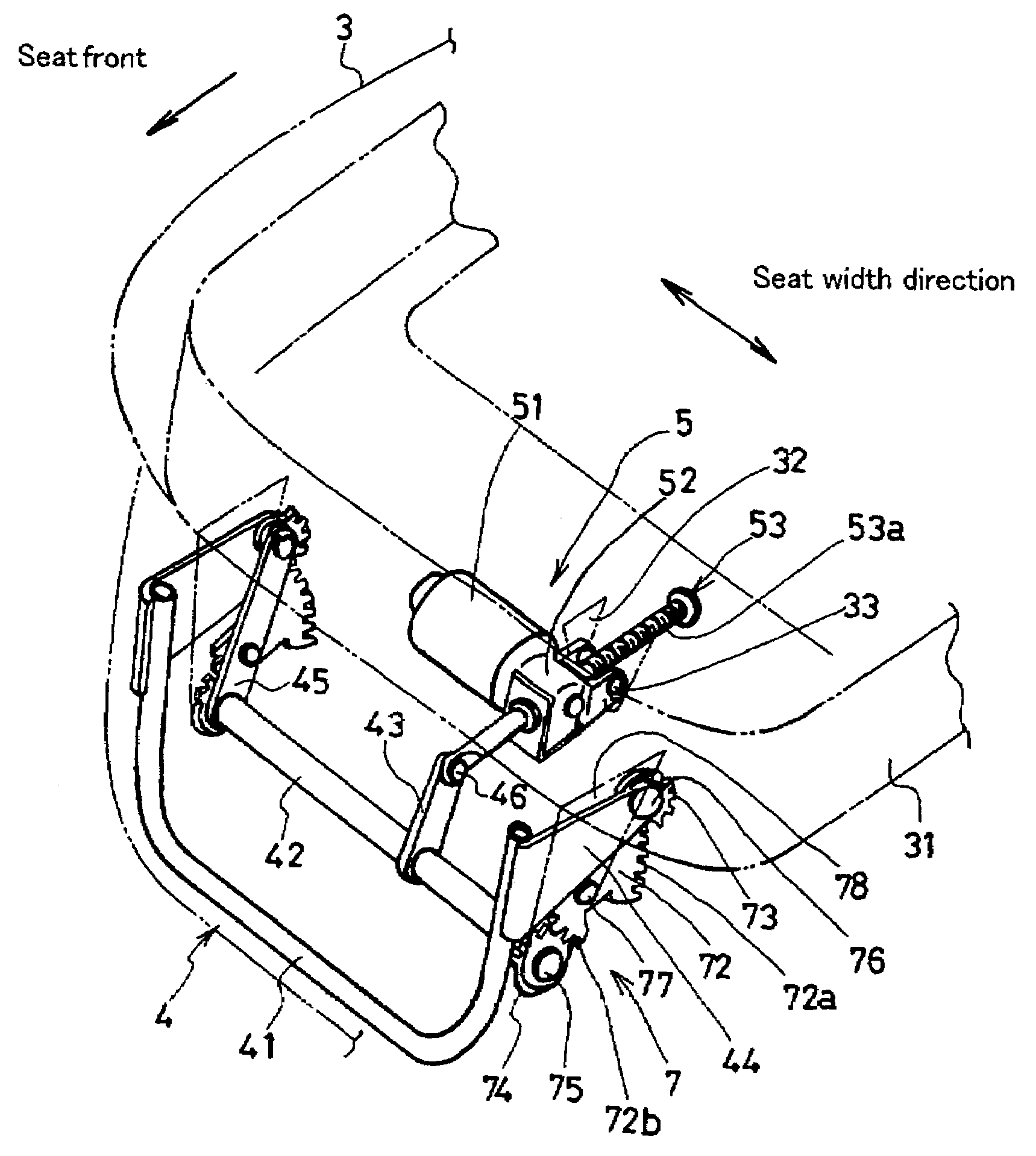
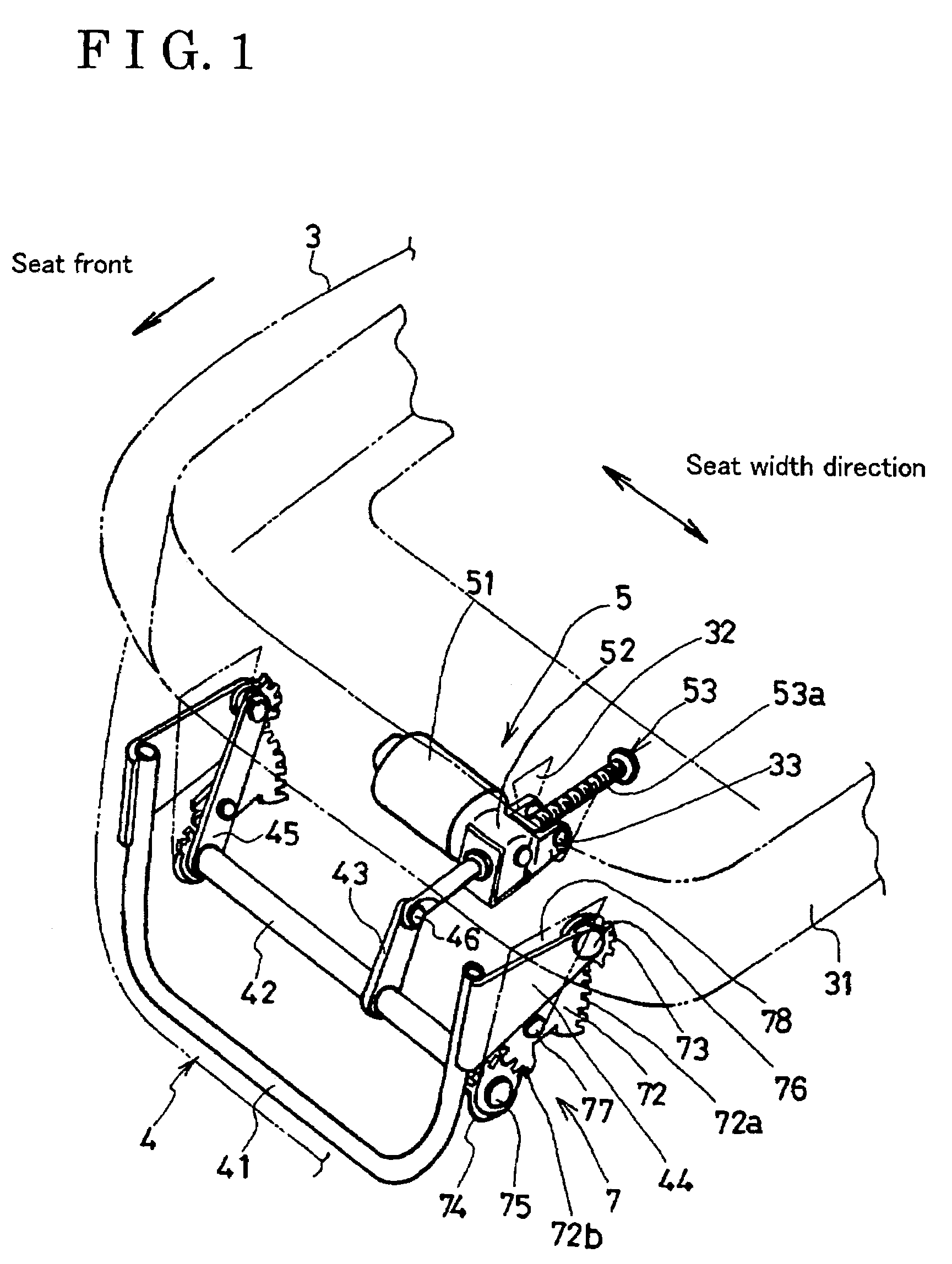
[0016]Embodiments of the present invention are explained referring to attached drawings FIG. 1 through FIG. 7. the present invention shown in FIG. 4 relates to the seat apparatus 1 including a collapsible footrest 4. The seat apparatus 1 also includes a seat back 2 and a seat cushion 3.

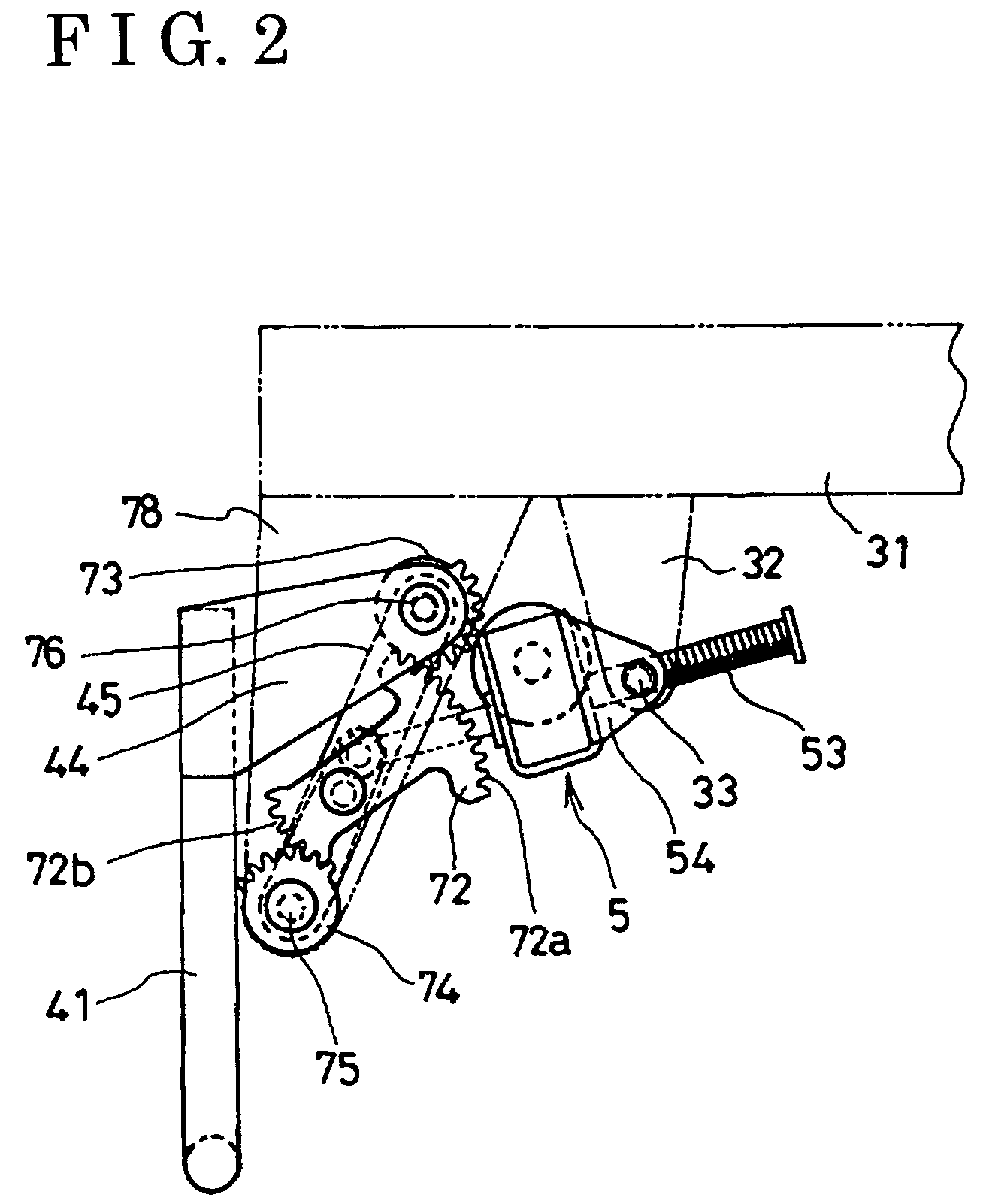
[0017]As shown in FIG. 1, the seat cushion 3 includes a cushion frame 31 as a structural member for enhancing the strength of the seat cushion 3. Further, a pair of brackets 78 is provided at an under surface of the front end of the cushion frame 31. The brackets 78 are spaced in a seat width direction.

[0018]The footrest 4 including a link mechanism 7 as a main subject of the present invention is supported to the bracket 78. The footrest 4 also includes a pair of arms 44 spaced in the seat width direction, and a U-shaped supporting member 41 extending in the seat width direction. The each end of the supporting member 41 is supported to the each arm 44. In such configuration, the footrest 4 is freely f...

second embodiment

[0027]Another example of the seat apparatus 10 being retractable as shown in FIG. 5 will be explained as the present invention.

[0028]In the second embodiment, the state of the seat apparatus 10 can be changed from the seating state to the retractable folded state. The seat apparatus 10 is supported by a front leg portion and a rear leg portion 170 to be stand on a vehicle floor in the seating state, and the seat apparatus 10 is housed in a concave portion 12 provided under the floor 12 in the retractable folded state. Such seat apparatus 10 includes the gear and link mechanism described in the first embodiment, which is applied to the rear leg portion 170. Thus, the seat apparatus 10 becomes retractable.

[0029]FIG. 6 indicates the rear leg portion 170 including the gear and link mechanism. As shown in FIGS. 5 and 6, a second gear 174a is provided at a supporting bracket 174 of the rear leg portion 170 installed on the floor 12. A transmitting gear 172 is rotatably supported by a supp...


PUM


Abstract

A seat apparatus for a vehicle includes supporting member and a moving member whose position is adjustable relative to the supporting member while a posture of the moving member is in a predetermined posture comprising a link member rotatably connected to the supporting member and the moving member respectively, a first gear secured to the moving member, a second gear secured to the supporting member and a transmitting gear rotatably supported to the link member. The transmitting gear includes a first partial gear meshing with the first gear and a second partial gear meshing with the second gear.

Description

CROSS REFERENCE TO RELATED APPLICATIONS[0001]This application is based on and claims priority under 35 U.S.C. § 119 to Japanese Patent Application 2003-198001, filed on Jul. 16, 2003, the entire content of which is incorporated herein by reference.FIELD OF THE INVENTION[0002]This invention generally relates to a seat apparatus including a link mechanism for changing a position of a part of the seat or folding a part of the seat, for example, a seat cushion, a leg portion, a footrest or a seat back. More particularly, the present invention pertains to a seat apparatus including a link mechanism for sufficiently changing the position of the part.BACKGROUND[0003]As an example of a device for sufficiently changing a position of a predetermined part of the seat, a known seat apparatus is disclosed in U.S. Pat. No. 6,095,610. The disclosed seat apparatus includes a link mechanism for changing a position of a footrest relative to the seat cushion. Such link mechanism basically includes a k...

Claims


Application Information

Patent Timeline
Patent Type & Authority Patents(United States)
IPC IPC(8): A47C20/00A47C7/50B60N2/02B60N2/22B60N2/23B60N2/30B60N2/90B60N3/06
CPCB60N2/0232B60N2/2213B60N2/233B60N2/3075B60N2/309B60N2/4495B60N2/995B60N2/02246
Inventor ITO, SADAO
Owner AISIN SEIKI KK
Learn More