
Linear vibration motor

a technology of linear vibration and motor, applied in the direction of motor/generator/converter stopper, electric controller, dynamo-electric converter control, etc., can solve the problems of high power supply unit capacity and size, high power supply unit voltage drop, and shortening the life of the power supply unit, so as to prevent whirring noise generation

Active Publication Date: 2007-06-26
MATSUSHITA ELECTRIC WORKS LTD
View PDF10 Cites 25 Cited by
  • Summary
  • Abstract
  • Description
  • Claims
  • Application Information

AI Technical Summary

Benefits of technology

[0017]An object of the present invention is to provide a linear vibration motor which does not make amplitude fluctuations and whirring noise, even when electric power is intermittently supplied.
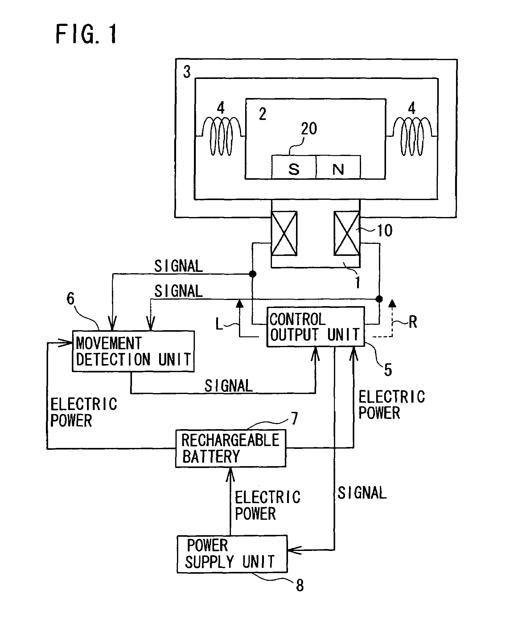
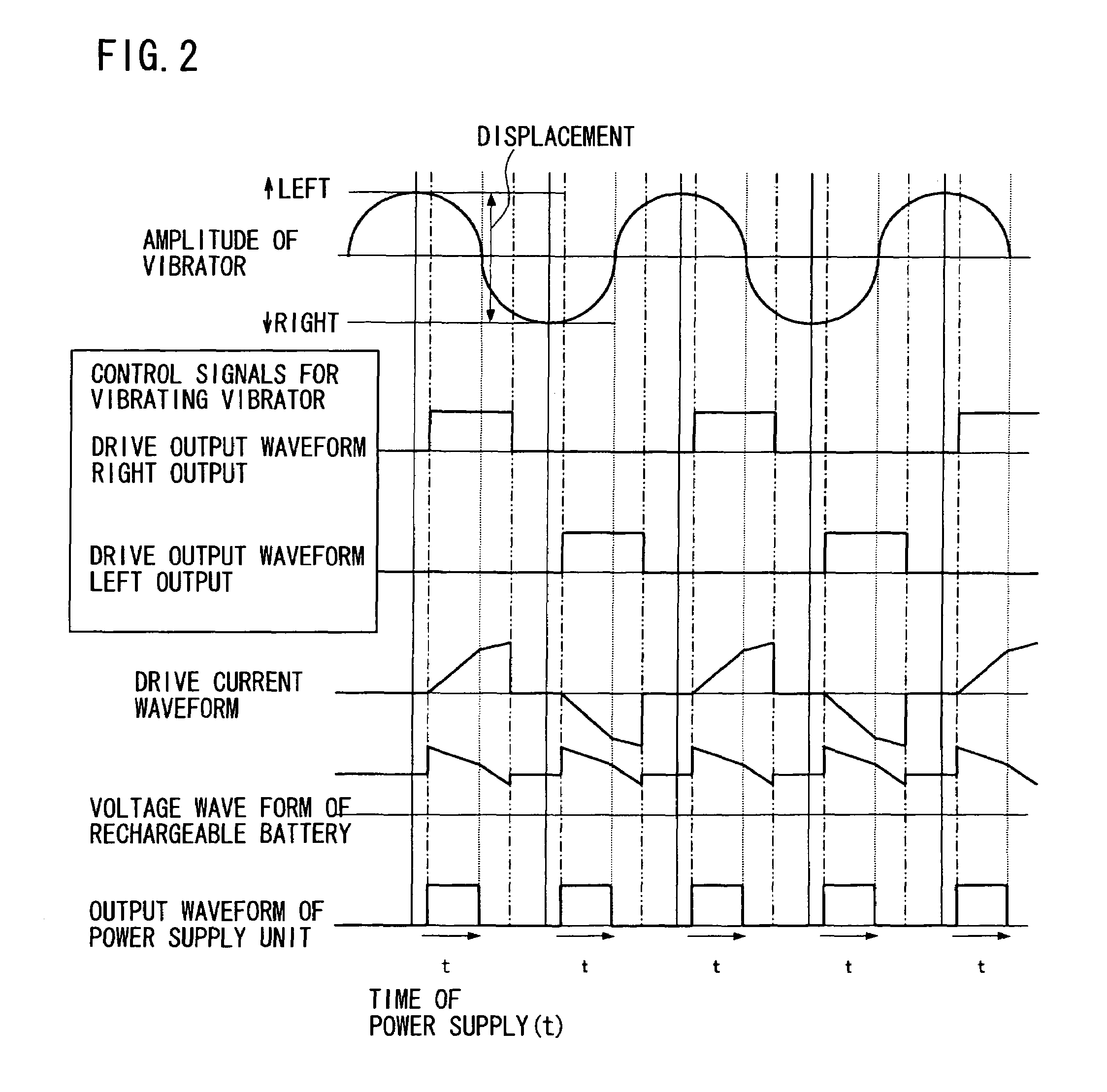
[0019]According to this linear vibration motor, the voltages of the rechargeable battery for left and right outputs to the winding become the same as each other at the timing of supplying electric power to the winding for left and right outputs, whereby amplitude variation caused by difference between the voltages of the rechargeable battery can be prevented.
[0025]According to the present invention, even when electric power is supplied to the rechargeable battery in an intermittent mode, the voltage of the rechargeable battery does not vary at the time of supplying electric power to the winding. Accordingly, amplitude fluctuations of the vibrator attributed to the rechargeable battery do not occur, thereby preventing whirring noise generation.

Problems solved by technology

However, in the case where the linear vibration motor uses a rechargeable battery as a power supply, a voltage drop of the rechargeable battery is likely to become a problem when it is operated for a long time.
In this case, if the power supply unit is designed assuming a large current to flow therethrough at the time of starting the operation or with heavy loads, the power supply unit is likely to become very large in capacity and size.
If the overcharge state further continues, it causes heat generation and fluid leakage of the rechargeable battery, thereby shortening its life.
However, such change causes the rechargeable battery voltage to increase as compared with that before the supply.
When the increase of amplitude displacement and the excessive amplitude reduction of the vibrator 102 are repeated, it causes amplitude fluctuations, which make a whirring noise.

Method used


Image

  • Linear vibration motor
  • Linear vibration motor
  • Linear vibration motor

Examples


Embodiment Construction

[0037]The best modes and preferred embodiments of the present invention will be described hereinafter with reference to the annexed drawings. The specific embodiments described are not intended to cover the entire scope of the present invention of the present invention, and hence the present invention is not limited to only the specific embodiments.

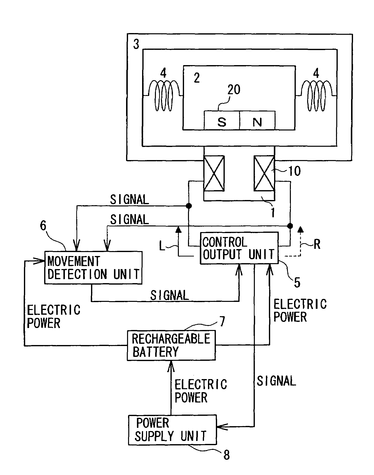
[0038]FIG. 1 shows a circuit diagram of the basic structure of a linear vibration motor according to an embodiment of the present invention. As shown in FIG. 1, the linear vibration motor comprises: a stator 1 provided with a winding 10 for forming an electromagnet; a vibrator 2 provided with a permanent magnet 20; a frame 3 for holding the vibrator 2; springs 4 connected between the frame 3 and the vibrator 2 for suspending the vibrator 2 so that the vibrator 2 is supported to be able to vibrate; a control output unit 5 for supplying a drive current to the winding 10; and a movement detection unit 6 for detecting the movement of the vibr...


PUM


Abstract

A linear vibration motor comprises: a stator provided with one of a permanent magnet and an electromagnet including a winding; a vibrator provided with the other of the permanent magnet and the electromagnet and supported to be able to vibrate; a movement detection unit for detecting movement of the vibrator; a control output unit for supplying electric power to the winding of the electromagnet based on an output of the movement detection unit so as to generate vibration of the vibrator; a rechargeable battery for supplying electric power to the control output unit; and a power supply unit for supplying electric power to the control output unit and to the rechargeable battery, wherein the power supply unit supplies electric power in an intermittent mode with synchronized timing such that the timing of the intermittent power supply is synchronized with the timing of the power supply to the winding. Thereby, the voltages of the rechargeable battery for left and right outputs to the winding become the same as each other at the timing of supplying electric power to the winding for left and right outputs, preventing amplitude variation caused by difference between the voltages of the rechargeable battery, and thereby preventing amplitude fluctuations and whirring noise.

Description

BACKGROUND OF THE INVENTION[0001]1. Field of the Invention[0002]The present invention relates to a linear vibration motor for generating reciprocating vibration, and more particularly to a linear vibration motor using a rechargeable battery as a power source.[0003]2. Description of the Related Art[0004]A conventional linear vibration motor, as disclosed in U.S. Pat. No. 6,351,089, which can be used as a drive source for a reciprocating type electric shaver is controlled in operation such that movement (displacement, velocity or acceleration) of a vibrator is detected so as to continuously generate a constant amplitude vibration even with load fluctuations, thereby generating a reciprocating movement with stable amplitude.[0005]FIG. 9 shows a circuit diagram of a conventional linear vibration motor. As shown in FIG. 9, the conventional linear vibration motor comprises: a stator 101 provided with a winding 110; a vibrator 102 provided with a permanent magnet 120; a frame 103 for holdi...

Claims


Application Information

Patent Timeline
Patent Type & Authority Patents(United States)
IPC IPC(8): H02P1/00H02P25/02H02P25/06H02P25/064
CPCH02P25/027H02P25/032
Inventor OBA, TAKAFUMITAKAHASHI, ATSUSHI
Owner MATSUSHITA ELECTRIC WORKS LTD
Learn More