Optical transmission device using a wide input dynamic range optical amplifier

a transmission device and dynamic range technology, applied in electromagnetic transmission, transmission monitoring, electromagnetic repeaters, etc., can solve the problems of wavelength dependence, varies in span loss, and difficulty in maintaining a low nf, so as to reduce optical loss, wide input dynamic range, and take a large osnr

Inactive Publication Date: 2007-07-24
FUJITSU LTD
View PDF6 Cites 10 Cited by
  • Summary
  • Abstract
  • Description
  • Claims
  • Application Information

AI Technical Summary

Benefits of technology

[0016]An object of the present invention is to provide an optical transmission device comprising an optical amplifier, which can secure a wide input dynamic range, and can take a large OSNR.
[0018]According to the present invention, the variable branching unit that can vary its branch ratio used to adjust an input level to the optical amplifying unit. Accordingly, an optical coupler having a conventional configuration, and a function of an optical attenuator can be comprised together, whereby an optical loss can be decreased by the amount of a loss in the optical attenuator, the OSNR of the optical amplifying unit can be improved, and a wide input dynamic range can be maintained as with a conventional technique.
[0019]According to the present invention, an optical transmission device having an optical amplifier, which can take a large OSNR while securing a wide input dynamic range, can be provided.

Problems solved by technology

Eventually, it is difficult both to maintain a low NF, namely, to suppress occurring noise and reduce wavelength dependence, and to widely secure the input dynamic range of the optical amplifier.
Furthermore, a span loss varies due to fluctuations in a temperature, etc.
Besides, a span loss may vary due to a problem transfer (a line change for coping with a road construction, etc.), or the like.
Namely, since the loss and the OSNR make a one-to-one correspondence, losses in the above described optical components result in a deterioration in the OSNR.
As described above, the OSNR of an output signal of the optical amplifier unit deteriorates due to losses in the optical components within the optical amplifier unit.

Method used


Image

  • Optical transmission device using a wide input dynamic range optical amplifier
  • Optical transmission device using a wide input dynamic range optical amplifier
  • Optical transmission device using a wide input dynamic range optical amplifier

Examples


Embodiment Construction

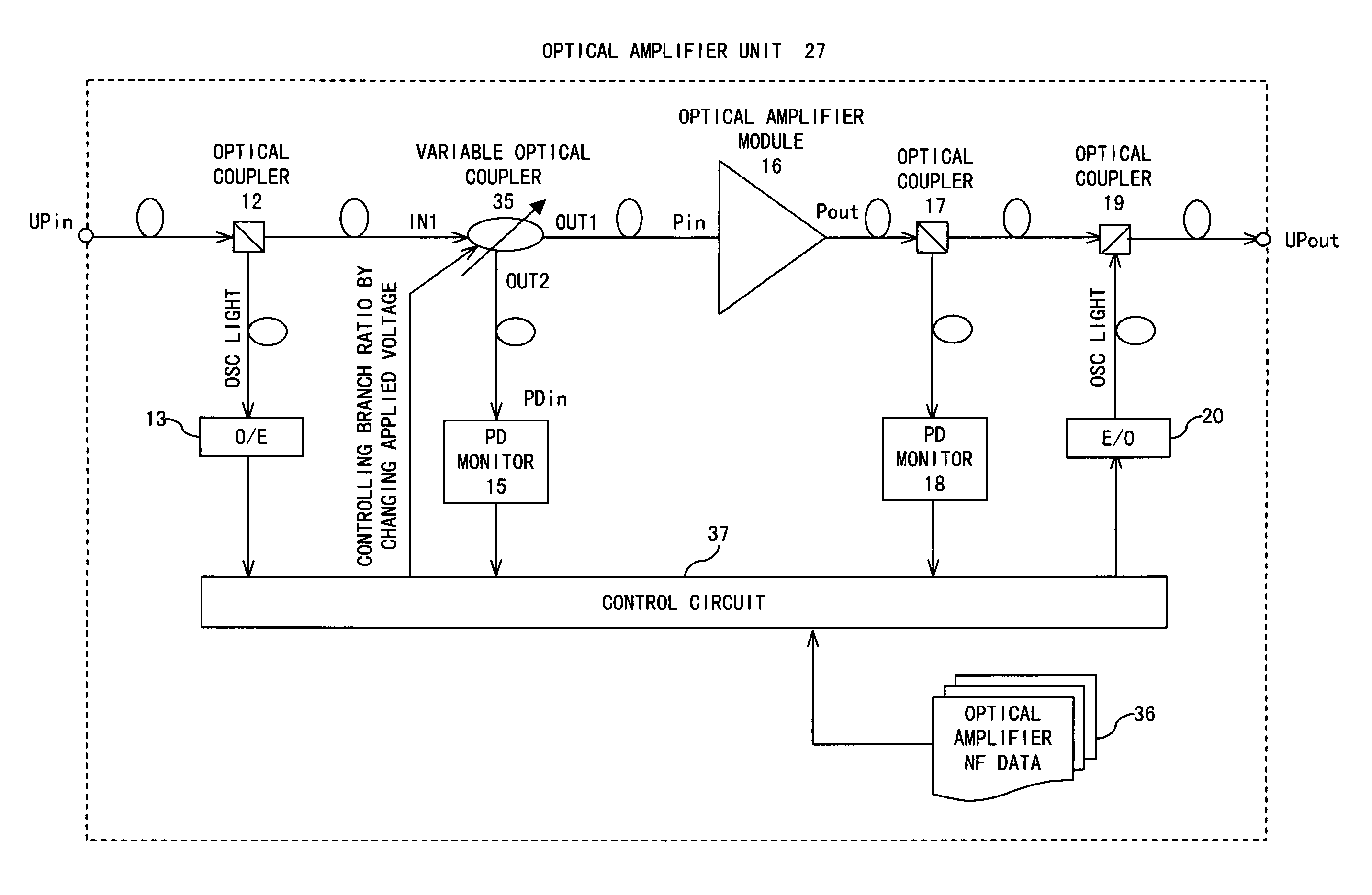
[0038]A system configuration to which a preferred embodiment according to the present invention is applied, the configuration of an optical amplifier unit according to the preferred embodiment of the present invention, and a control flow according to the preferred embodiment of the present invention are respectively shown in FIGS. 4, 5, and 6.

[0039]In FIG. 4, optical signals having respective wavelengths transmitted from an OS (Optical Sender) 25 are multiplexed by a multiplexer 26, and transmitted to a transmission line as an optical wavelength division multiplexed signal. Optical amplifier units 27 each comprising a DCF (Dispersion Compensation Fiber) 28 provided for wavelength dispersion are arranged at predetermined intervals on the transmission line configured by an optical fiber. An interval between optical amplifier units 27 is called a span, and an intensity loss in an optical signal, which occurs in one span, is called a span loss. The optical wavelength division multiplexe...


PUM


Abstract

Conventionally, an adjustment of an optical power level of an input Pin of an optical amplifier module is made with an optical variable attenuator. An optical coupler for measuring the optical power level of Pin and an optical variable attenuator are replaced by a variable optical coupler. The branch ratio of the variable optical coupler is varied, whereby the input optical power level Pin to an optical amplifier module is adjusted. As a result, an optical loss is reduced by an amount corresponding to the elimination of the optical attenuator, and also the OSNR of the optical amplifier module is improved.

Description

BACKGROUND OF THE INVENTION[0001]1. Field of the Invention[0002]The present invention relates to an optical transmission device having an optical amplifier in a WDM (Wavelength Division Multiplexing) apparatus.[0003]2. Description of the Related Art[0004]FIGS. 1A and 1B explain a conventional technique.[0005]Normally, a noise figure (hereinafter abbreviated to an NF) of an optical amplifier for WDM tends to increase with an increase in the input level of the amplifier if its output is made constant. FIG. 1A shows the state of an increase in the NF of an optical amplifier module. Pin is an input level of light input to the optical amplifier module, and indicates an optical intensity per channel. This figure indicates that the NF nonlinearly increases with an increase in Pin over the entire input dynamic range of the optical amplifier module. In the meantime, FIG. 1B indicates a relationship between Pin and an OSNR (Optical Signal-to-Noise Ratio). The OSNR exhibits an upward convex cu...

Claims


Application Information

Patent Timeline
Patent Type & Authority Patents(United States)
IPC IPC(8): H04B10/16H01S3/10H04B10/07H04B10/25H04B10/29H04B10/294
CPCH04B10/2931
Inventor MAEDA, TAIZOFUJITA, TAKEHIROSEKIYA, MOTOYOSHI
Owner FUJITSU LTD
Why Eureka
Try Eureka