Dual dimple surface geometry for a golf ball

a golf ball and surface geometry technology, applied in the field of aerodynamic surface geometry of golf balls, can solve the problems of non-traditional golf balls that have been commercially unsuccessful

Active Publication Date: 2007-07-31
AMERICAN SPORTS LICENSING
View PDF7 Cites 31 Cited by
  • Summary
  • Abstract
  • Description
  • Claims
  • Application Information

AI Technical Summary

Problems solved by technology

Many golf balls have been disclosed that break with this tradition, however, for t

Method used


Image

  • Dual dimple surface geometry for a golf ball
  • Dual dimple surface geometry for a golf ball
  • Dual dimple surface geometry for a golf ball

Examples


Embodiment Construction

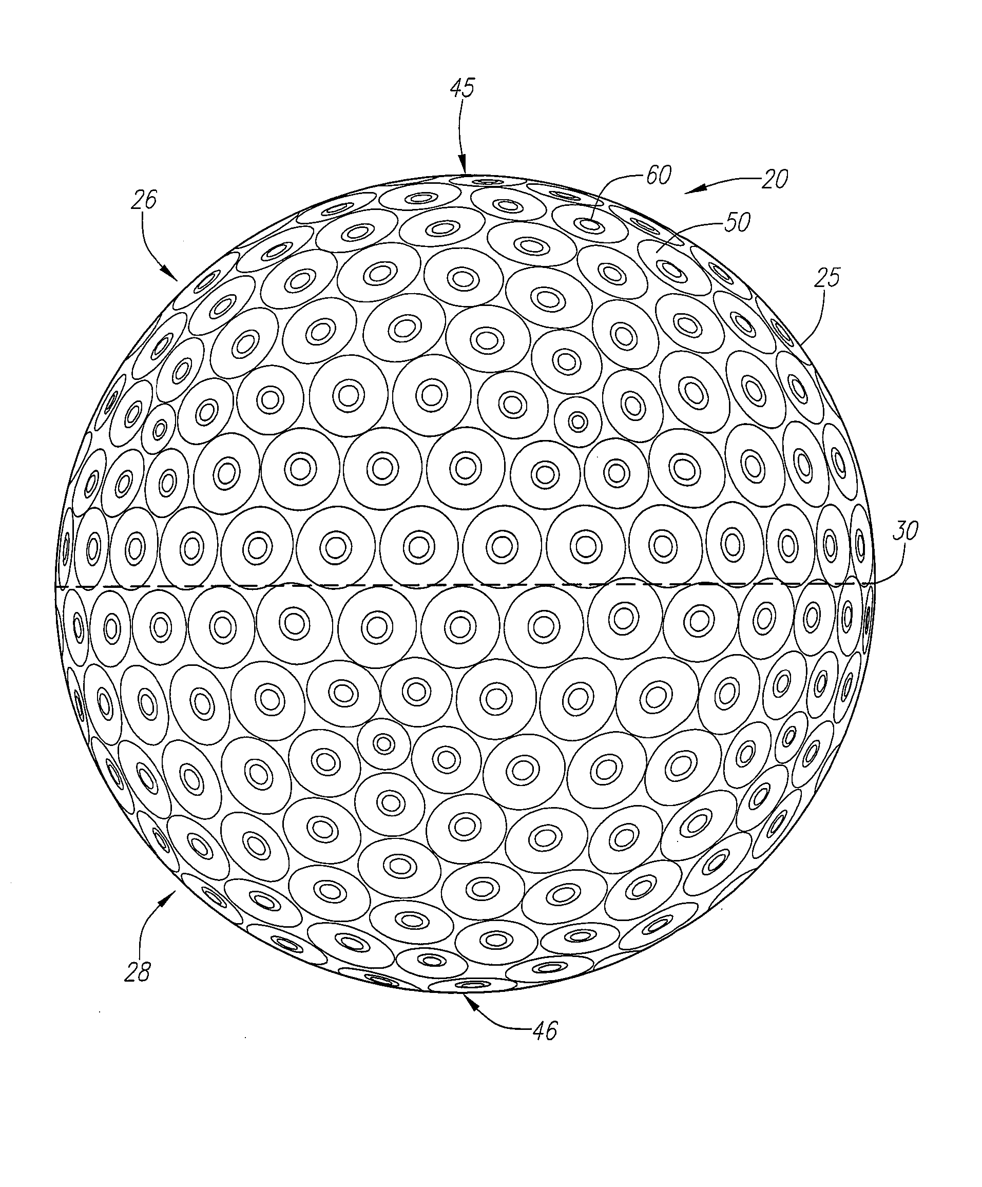
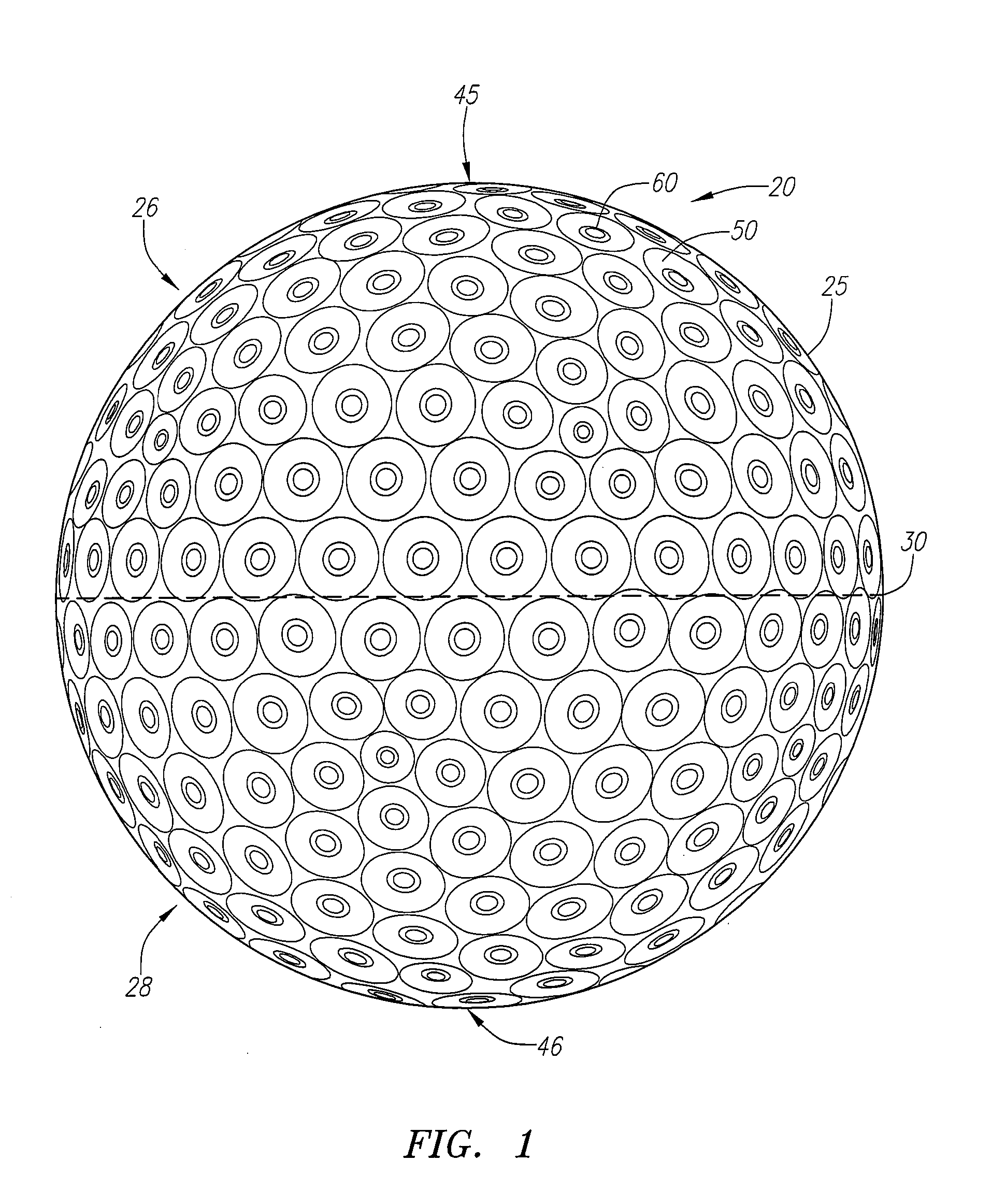
[0039]As shown in FIGS. 1-4, a golf ball is generally designated 20. The golf ball 20 may be a two-piece golf ball, a three-piece golf ball, or a multi-layer golf ball with more than three layers. The construction of the golf ball is discussed in greater detail below.

[0040]The golf ball 20 has a surface 25. The golf ball 20 also has an equator 30 dividing the golf ball 20 into a first hemisphere 26 and a second hemisphere 28. A first pole 45 is located ninety degrees along a longitudinal arc from the equator 30 in the first hemisphere 26. A second pole 46 is located ninety degrees along a longitudinal arc from the equator 30 in the second hemisphere 28.

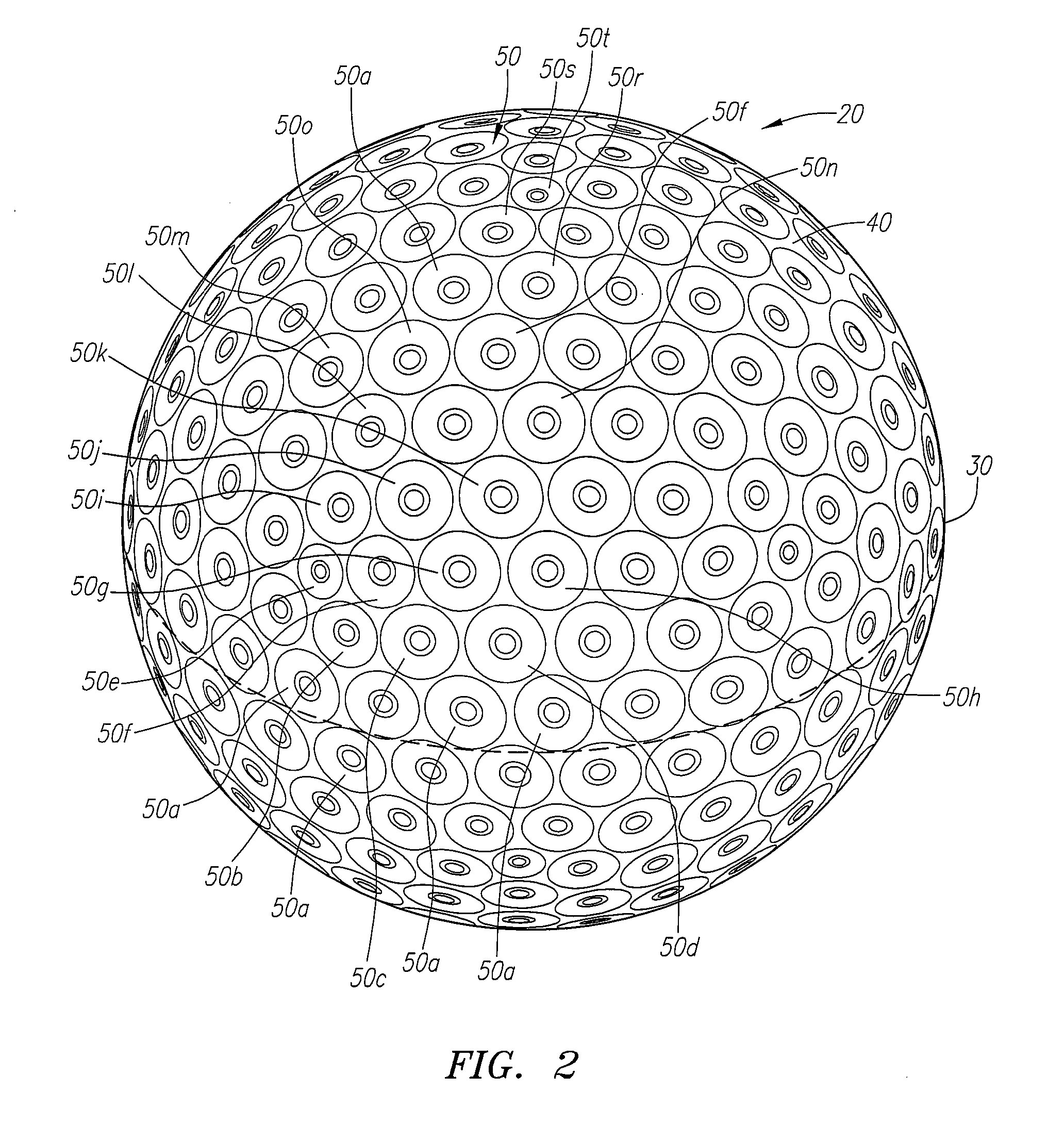
[0041]On the surface 25, there are preferably 332 primary dimples 50 partitioned into twenty different sets of primary dimples 50a-50t. Each of the primary dimples has an annular tubular portion 60 within the dimple surface area 55 of the primary dimple 50. Each of the annular tubular portions 60 lies below a chord depth of its primar...


PUM


Abstract

A golf ball (20) having a plurality of primary dimples (50) with annular tubular portion (60) is disclosed herein. In a preferred embodiment, there are 332 primary dimples which cover a surface area ranging from 81% to 87% of the golf ball (20). Also in a preferred embodiment, there are twenty different types of primary dimples (50), which vary in diameter, chord depth and/or entry angle.

Description

CROSS REFERENCES TO RELATED APPLICATIONS[0001]The Present application claims priority to U.S. Provisional Patent Application No. 60 / 806,955, filed on Jul. 11, 2006.STATEMENT REGARDING FEDERALLY SPONSORED RESEARCH OR DEVELOPMENT[0002]Not ApplicableBACKGROUND OF THE INVENTION[0003]1. Field of the Invention[0004]The present invention relates to an aerodynamic surface geometry for a golf ball. More specifically, the present invention relates to a golf ball having a dual dimple surface geometry.[0005]2. Description of the Related Art[0006]Golfers realized perhaps as early as the 1800's that golf balls with indented surfaces flew better than those with smooth surfaces. Hand-hammered gutta-percha golf balls could be purchased at least by the 1860's, and golf balls with brambles (bumps rather than dents) were in style from the late 1800's to 1908. In 1908, an Englishman, William Taylor, received a British patent for a golf ball with indentations (dimples) that flew better and more accuratel...

Claims


Application Information

Patent Timeline
IPC IPC(8): A63B37/12
CPCA63B37/0004A63B37/12A63B37/001A63B37/0015A63B37/0018A63B37/0019A63B37/002A63B37/0021A63B37/0022A63B37/0033A63B37/0074A63B37/0075A63B37/0076
Inventor SIMONDS, VINCENT J.BERGIN, THOMAS F.VEILLEUX, THOMAS A.MUHLANGER, ERICH
Owner AMERICAN SPORTS LICENSING
Why Eureka
Try Eureka