Optical power switch

a power switch and optical radiation technology, applied in the field of optical radiation limiters, can solve the problems of low dynamic range of protective devices made from these materials, high vulnerability to damage, and inability to fully protect detector materials, etc., and achieve low switching threshold, low dynamic range, and low resistance.

a power switch and optical radiation technology, applied in the field of optical radiation limiters, can solve the problems of low dynamic range of protective devices made from these materials, high vulnerability to damage, and inability to fully protect detector materials, etc., and achieve low switching threshold, low dynamic range, and low resistance.

US7259925B1Inactive Publication Date: 2007-08-21ARMY US SEC THE

Image

  • Optical power switch
  • Optical power switch

Examples


Embodiment Construction

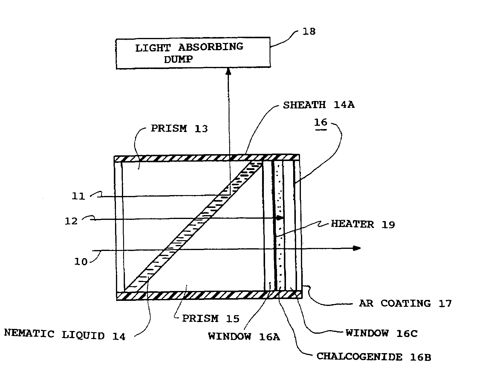
[0009]FIG. 1 shows a detailed view of a first embodiment of applicant's novel protective device. This device utilizes a high power limiter such as one disclosed in an earlier application entitled Frustrated Total Internal Reflection Power Limiter, Ser. No. 648,140 filed 5 Sep. 1984. As disclosed in that application, the limiter must be located at an intermediate focal point, which can be created by adding beam folding mirrors to a first generation FLIR, but which is an integral feature of second generation FLIRS. A similar device is disclosed in Ser. No. 268,461 “Optical Power Limiter Utilizing Nonlinear Refraction”, filed 1 Nov. 1989 by Gary L. Wood, et al. The operation of the components, 13, 14, 15, and 17 are essentially described in the earlier patent applications. For example, a low / intensity ray 10, representing ambient IR levels at which the FLIR detector is designed to operate is transmitted undeviated and substantially unattenuated through the protective limiter device. Th...


PUM


Abstract

The present invention provides a protective device for sensitive infrared sensors as Forward Looking Infrared imagers (FLIRs). A prior device using materials with higher order susceptibilities to electric polarization, which provides protection against extremely intense radiation from high-power lasers is combined with a low energy optical power limiters such as the chalcogenide glass and the vanadium dioxide which respond reversibly to infrared radiation.

Description

[0001]The invention described herein may be manufactured, used, and licensed by the U.S. Government for governmental purposes without the payment of any royalties thereon.BACKGROUND OF INVENTION[0002]1. Field[0003]This invention pertains to optical radiation limiters used as protective devices for imaging devices such as the FLIR (Forward Looking Infrared Imager).[0004]2. Prior Art[0005]Far infrared imagers must be highly sensitive in order to operate with the small temperature differentials that define many targets. Because of their sensitivity and the material used for such detector elements, e.g. mercury cadmium telluride, they are highly vulnerable to damage from low energy threat laser radiation. In an earlier patent application entitled, “Frustrated Total Internal Reflection Optical Power Limiter (FTIR)”, Ser. No. 648,140, a high energy protective device, using, e.g. nematic liquid crystals, is described, which limits the input radiation, if it exceeds a certain level, thus pr...

Claims


Application Information

Patent Timeline
21 Aug 2007
Publication
US7259925B1
IPC
G02B7/00
CPC
G02F1/132; G02F1/19
Inventors
AHN, BYONG H.