Method for forming sheet material with bend controlling grooves defining a continuous web across a bend line

a technology of bend control and continuous web, which is applied in the direction of metal-working feeding devices, forging/pressing/hammering devices, handling devices, etc., can solve the problem of less precision in the location of bend lines

Inactive Publication Date: 2007-09-04
IND ORIGAMI INC CA US
View PDF74 Cites 41 Cited by
  • Summary
  • Abstract
  • Description
  • Claims
  • Application Information

AI Technical Summary

Problems solved by technology

The approach results in a bend line which has less precision in its location than would be otherwise desirable.

Method used


Image

  • Method for forming sheet material with bend controlling grooves defining a continuous web across a bend line
  • Method for forming sheet material with bend controlling grooves defining a continuous web across a bend line
  • Method for forming sheet material with bend controlling grooves defining a continuous web across a bend line

Examples


Embodiment Construction

[0027]Reference will now be made in detail to the preferred embodiments of the present invention, examples of which are illustrated in the accompanying drawings. While the invention will be described in connection with the preferred embodiments, it will be understood that the illustrated embodiments are not intended to limit the invention. On the contrary, the invention is intended to cover alternatives, modifications and equivalents, which may be included within the spirit and scope of the invention, as defined by the appended claims.

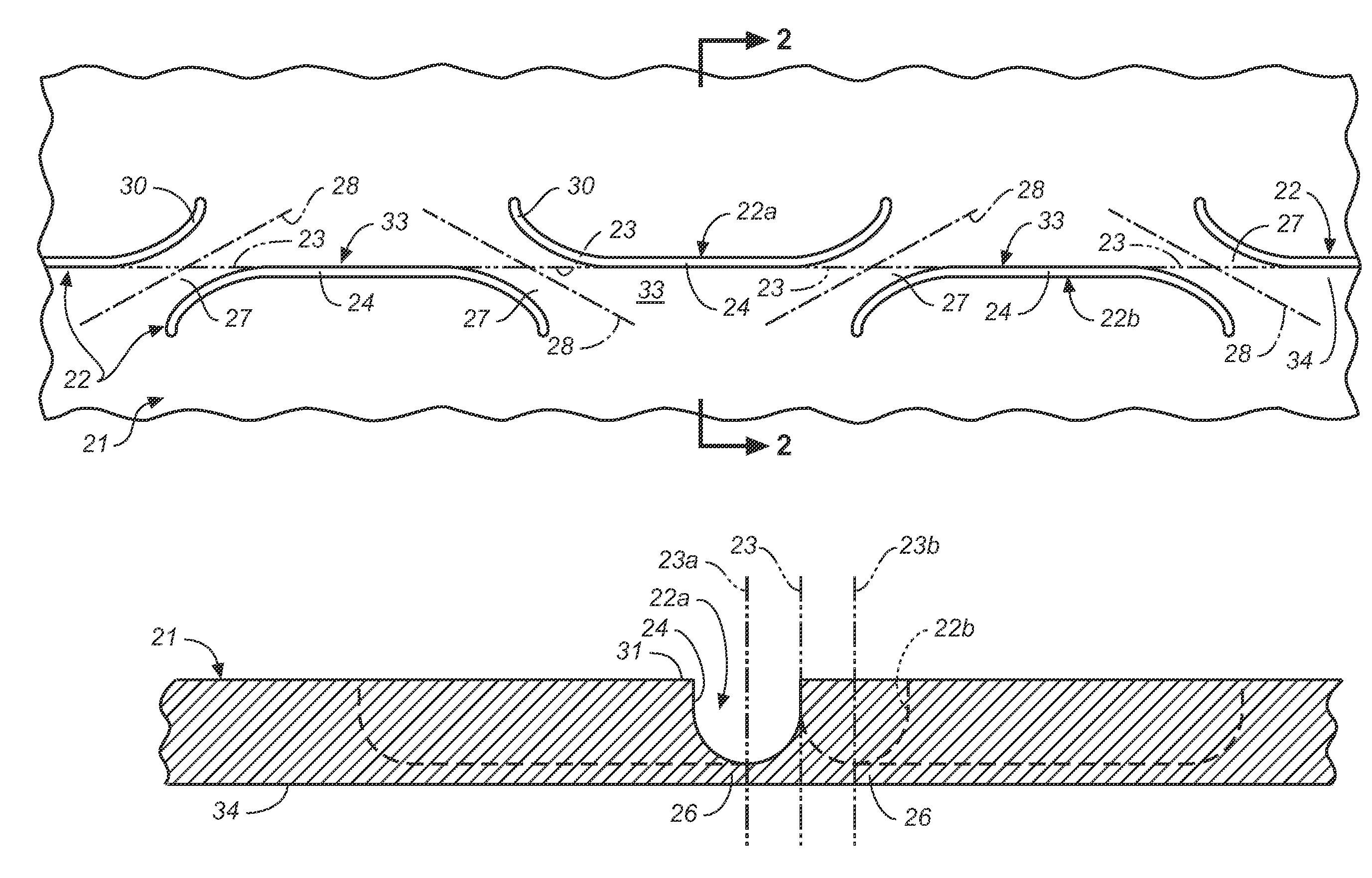
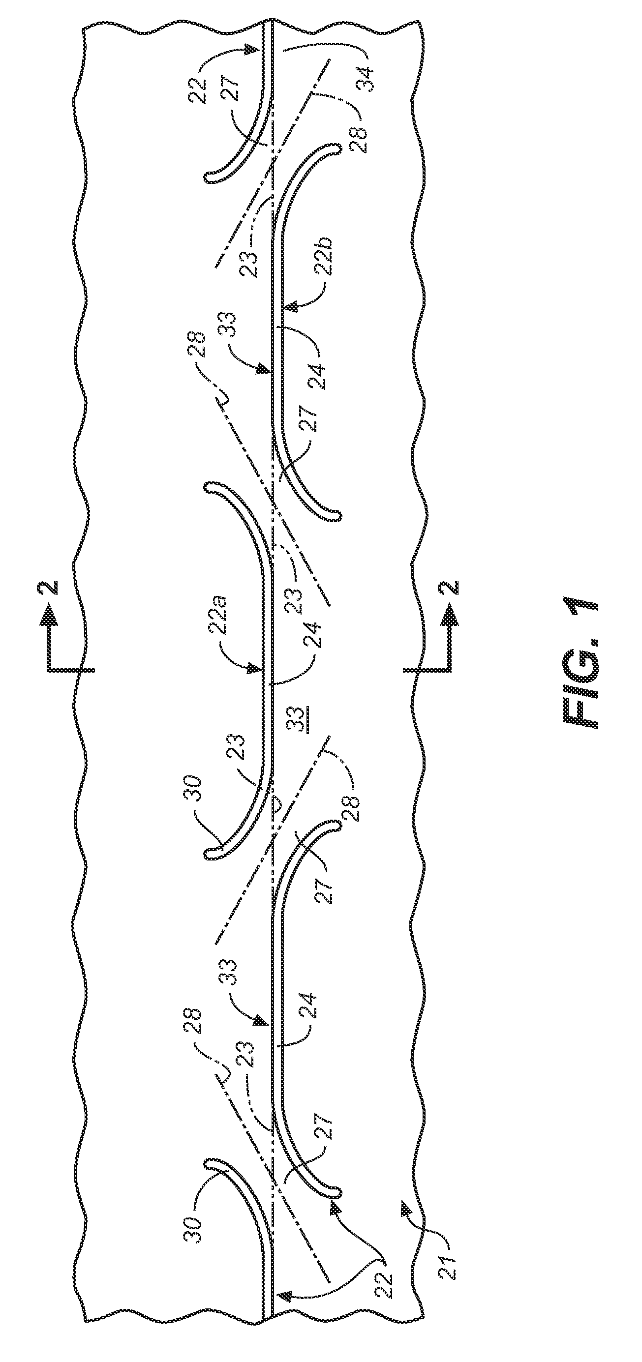
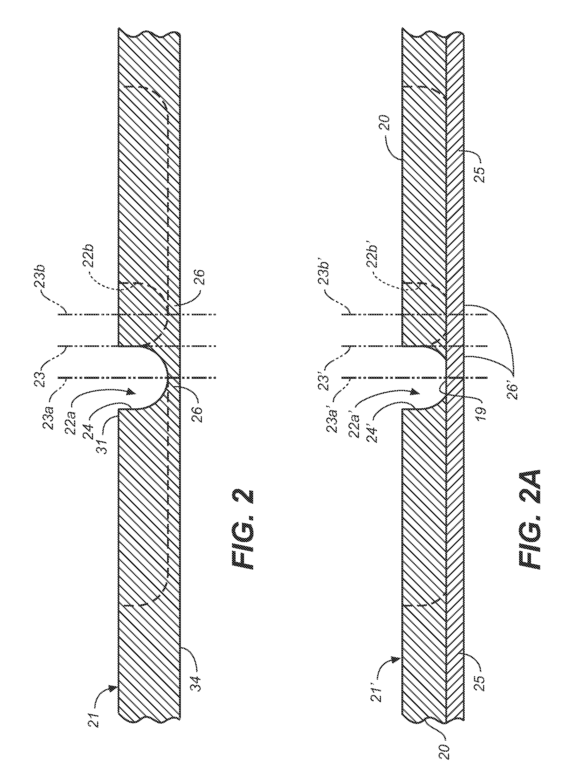
[0028]Referring now to FIGS. 1, 2 and 3A, a sheet of material 21 can be seen to be formed with at least one groove, and as illustrated, with a plurality of grooves 22 along a sheet bend line 23. Grooves 22 extend longitudinally along, and are preferably placed on alternating sides of, bend line 23, with adjacent grooves being in a longitudinally shifted or displaced relationship, as one proceeds longitudinally along the bend line. Each groove 22 has a ...


PUM

PropertyMeasurementUnit
forcesaaaaaaaaaa
lengthaaaaaaaaaa
thicknessaaaaaaaaaa

Abstract

A sheet of material (21, 61, 81) formed for control bending along a bend line (23, 63) while maintaining a continuous web of material (26) across the bend line (23, 63). The sheet has at least one groove (22, 62, 82) formed therein with a central groove portion (24, 64, 84) extending in the direction of and positioned proximate to a desired bend line (23, 63). The groove is formed with a continuous web of material (26) at a bottom of the groove (22, 62, 82) and has a configuration defining at least one bending strap (27, 67) extending across the bending line (23, 63) at the end of the groove with a centerline (28) of the bending strap (27, 67) oriented obliquely across the bend line (23, 63) so that a balancing of the forces during bending of the web along the central portion (24, 64, 84) of the grooves and bending of the oblique bending strap occur and control the location of bending of the sheet. A method of preparing a sheet of material (21, 61, 81) for bending while maintaining a continuous membrane (26) across the bend line (23, 63) is also disclosed.

Description

RELATED APPLICATIONS[0001]This application is a continuation-in-part application based upon a patent application Ser. No. 10 / 795,077, filed Mar. 3, 2004, now U.S. Pat. No. 7,152,450, and entitled Sheet Material with Bend Controlling Displacements and Method for Forming the Same, which is a continuation-in-part application based upon patent application Ser. No. 10 / 256,870, filed Sep. 26, 2002, now U.S. Pat. No. 6,877,349 and entitled Method for Precision Bending of Sheet Materials, Slit Sheet and Fabrication Process, which was a continuation-in-part application based upon a parent application Ser. No. 09 / 640,267, filed Aug. 17, 2000, and entitled Method for Precision Bending of a Sheet of Material and Slit Sheet Therefor, now U.S. Pat. No. 6,481,259 B1.TECHNICAL FIELD[0002]The present invention relates, in general, to precision bending or folding of sheet material, and more particularly, relates to preparing sheet material for bending by grooving the same so that a continuous web or ...

Claims


Application Information

Patent Timeline
Patent Type & Authority Patents(United States)
IPC IPC(8): B21D28/00B32B3/30B21D5/00
CPCB21D5/00B21D11/20B32B3/10E04C2/08E04C2/26Y10T428/24479Y10T428/24264Y10T428/15Y10T428/24314Y10T428/2457B32B3/30B21D28/00B32B2457/08B32B7/12
Inventor DURNEY, MAX W.HOLMAN, RICK A.ARNOLD, PHILIP M.
Owner IND ORIGAMI INC CA US
Why Eureka
Try Eureka