
Image projector display device

a projector and display device technology, applied in the field of projecting images, can solve the problems that the arrangement of either the slide projector or the overhead projector, however, is not suitable for projecting images onto the surface, and achieves the effect of avoiding disadvantages and drawbacks

Active Publication Date: 2007-09-11
BE SEEN SOLUTIONS
View PDF9 Cites 30 Cited by
  • Summary
  • Abstract
  • Description
  • Claims
  • Application Information

AI Technical Summary

Benefits of technology

[0012]The invention avoids the disadvantages and drawbacks of the related art by allowing a proper display of an image.

Problems solved by technology

The arrangement of either the slide projector or the overhead projector, however, would not be suitable for projecting an image onto a surface that is substantially parallel to the direction of light projected to display an image.

Method used


Image

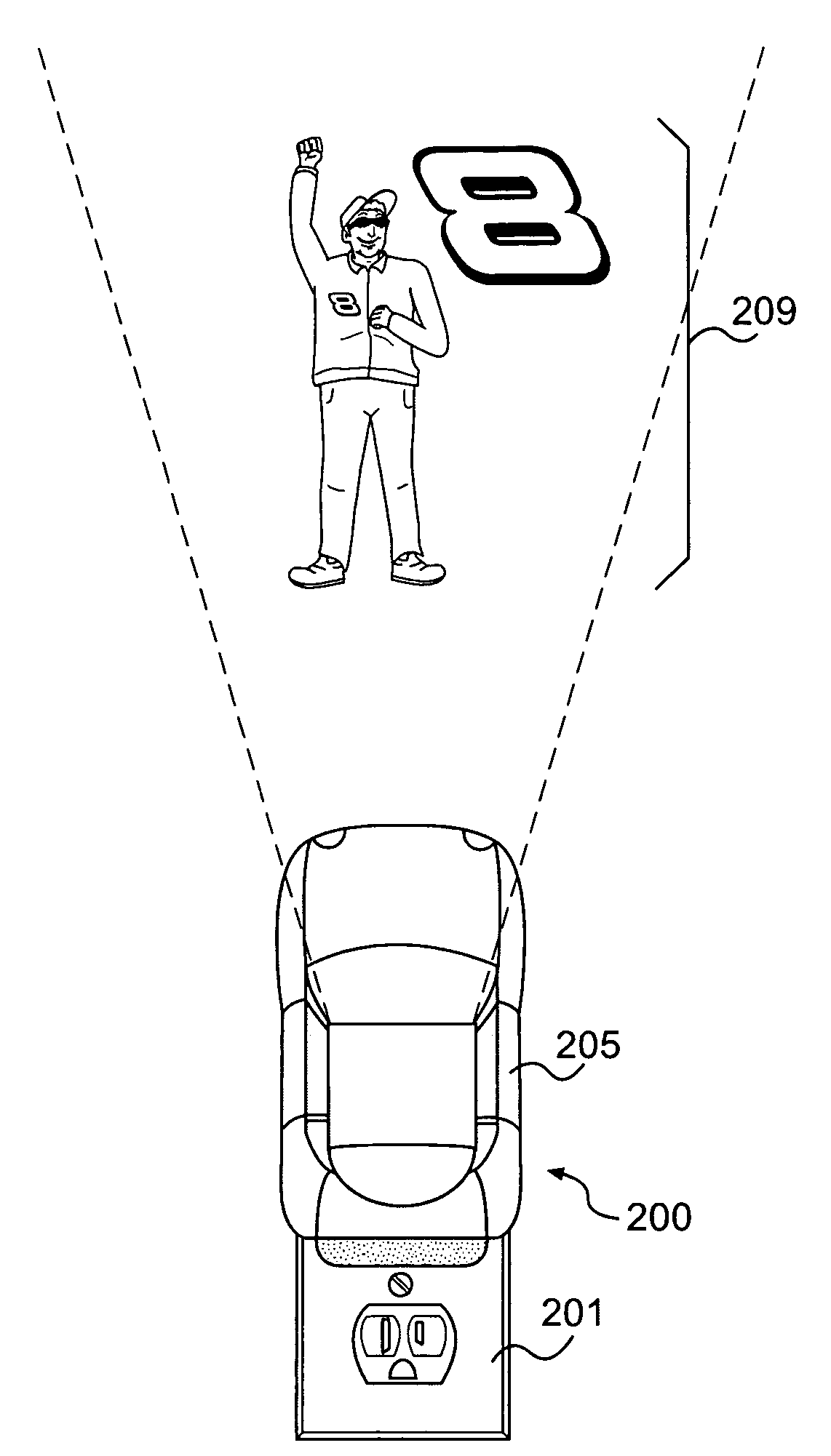
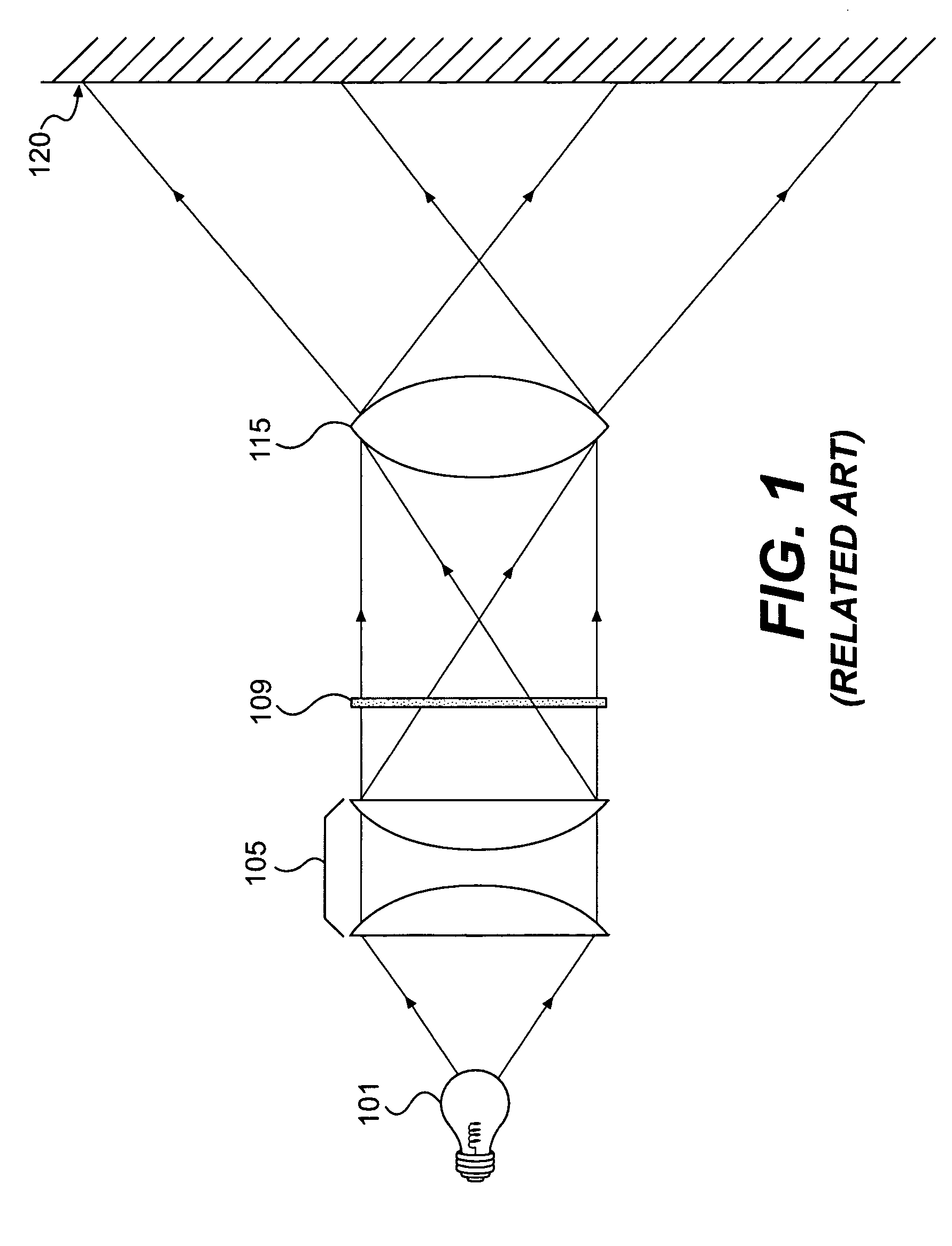
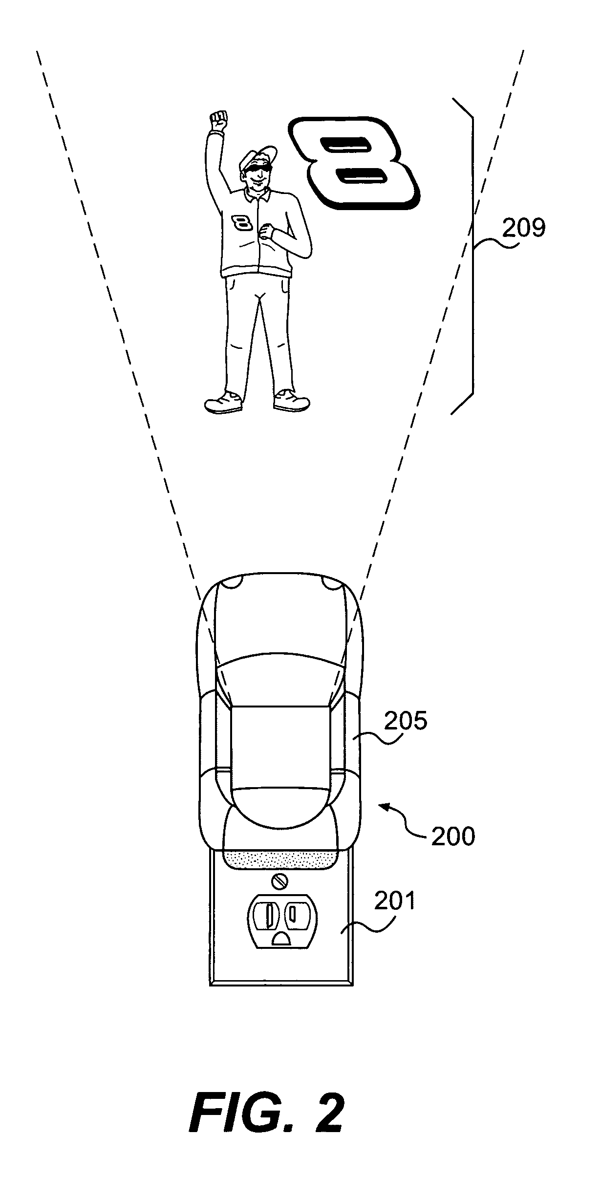
  • Image projector display device
  • Image projector display device
  • Image projector display device

Examples


Embodiment Construction

[0027]The embodiments of the invention and the various features and advantageous details thereof are explained more fully with reference to the non-limiting embodiments and examples that are described and / or illustrated in the accompanying drawings and detailed in the following description. It should be noted that the features illustrated in the drawings are not necessarily drawn to scale, and features of one embodiment may be employed with other embodiments as the skilled artisan would recognize, even if not explicitly stated herein. Descriptions of well-known components and processing techniques may be omitted so as to not unnecessarily obscure the embodiments of the invention. The examples used herein are intended merely to facilitate an understanding of ways in which the invention may be practiced and to further enable those of skill in the art to practice the embodiments of the invention. Accordingly, the examples and embodiments herein should not be construed as limiting the s...


PUM


Abstract

An image projector display device projecting an image onto a surface substantially parallel to a path of light emitted through a representation of an image and a projection / objective lens. The display device compensates for the varying distances of the surface onto to which the image is projected from the projection / objective lens to display a clear, non-distorted image.

Description

CROSS-REFERENCE TO RELATED APPLICATION[0001]The application claims priority under 35 U.S.C. § 119(e) to U.S. Provisional Application No. 60 / 604,495, filed on Aug. 26, 2004, the disclosure of which is expressly incorporated by reference herein in its entirety.BACKGROUND OF INVENTION[0002]1. Field of the Invention[0003]The invention generally relates to projecting an image onto a surface that is substantially parallel to an axis of light passing through an objective lens, and more particularly to projecting an image from an image representation onto a surface where the angle from one portion of the image representation to the surface is different than the angle from at least one other portion of the image representation.[0004]2. Description of Related Art[0005]A typical image projector will shine a light source towards an image representation, such as a slide or transparency. The light then passes through an objective lens that will magnify the image representation to display an image...

Claims


Application Information

Patent Timeline
Patent Type & Authority Patents(United States)
IPC IPC(8): G03B21/14
CPCG03B21/00G03B21/14G03B21/147G03B21/001
Inventor BLACK, JR., FREDERICK STANLEY
Owner BE SEEN SOLUTIONS
Learn More