
Pneumatic tire for motorcycle

a technology for pneumatic tires and motorcycles, applied in the direction of non-skid devices, cycles, transportation and packaging, etc., can solve the problems of deteriorating steering stability, unsuitable machines, and the inability of tires 100/b> to provide effective block rigidity, etc., and achieve the effect of ensuring steering stability

Active Publication Date: 2007-09-18
BRIDGESTONE CORP
View PDF16 Cites 1 Cited by
  • Summary
  • Abstract
  • Description
  • Claims
  • Application Information

AI Technical Summary

Benefits of technology

The tire provides improved drainage performance, increased wear resistance, and enhanced steering stability on wet surfaces by maintaining contact with the road and distributing water effectively, while maintaining sufficient rigidity to handle cornering forces.

Problems solved by technology

However, the tire 100 cannot provide effective block rigidity, and has not been suitable for a machine that outputs a large power in respect of wear resistance.
In other words, when the tire 100 is used for a large power-outputting machine, edge portions of blocks 102 to 114 at a stamping side and at a kick-out side easily unevenly wear, thus deteriorating steering stability.
However, from a viewpoint of a ratio of a block pattern to a tire, it can be considered that drainage performance is poor due to a low negative rate, and grip sensation is not granted due to insufficient edge components.
However, during a motorcycle cornering, input directions are likely to incline with respect to a tire circumferential direction, and the larger the camber angle, the closer the input directions to a tire transverse direction.
Accordingly, a problem is caused in that uneven wear may easily occur due to an input exerted in a tire circumferential direction thereby deteriorating steering stability.
However, since angles of the inclining grooves 306 are fixed, rigidities of the land portions 308 become insufficient with respect to inputs during a motorcycle cornering at a large camber angle, and a problem is caused in that each tread end may easily unevenly wear thereby deteriorating steering stability due to an occurrence of uneven wear.

Method used


Image

  • Pneumatic tire for motorcycle
  • Pneumatic tire for motorcycle
  • Pneumatic tire for motorcycle

Examples


examples

[0228]In order to confirm effects of the present invention, a tire in Example to which the present invention was employed, two tires in Conventional Examples, and two tires in Comparative Examples are prepared to compare feeling evaluations at the times of braking, cornering, and traction of a motorcycle, and durabilities thereof.

[0229]Test tires will be explained hereinafter.

[0230]A tire in Example is a pneumatic tire for a motorcycle explained in the present embodiment.

[0231]A tire in Comparative Example 1 is a pneumatic tire for a motorcycle having a pattern shown in FIG. 5.

[0232]A tire in Comparative Example 1 is a pneumatic tire for a motorcycle having a pattern shown in FIG. 8. As shown in FIG. 8, in a tread 402 of a tire 400 in Comparative Example 1, a first inclining groove 404 which extends from a tread end to the tire equatorial plane CL and which terminates in the vicinity of the tire equatorial plane CL, and a second inclining groove 406 which is shorter than the first i...


PUM


Abstract

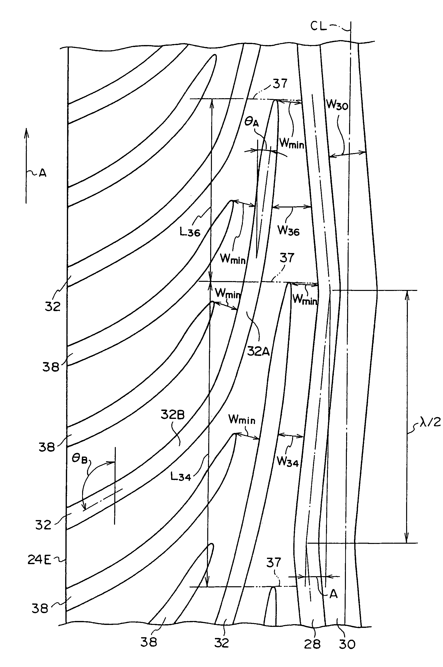
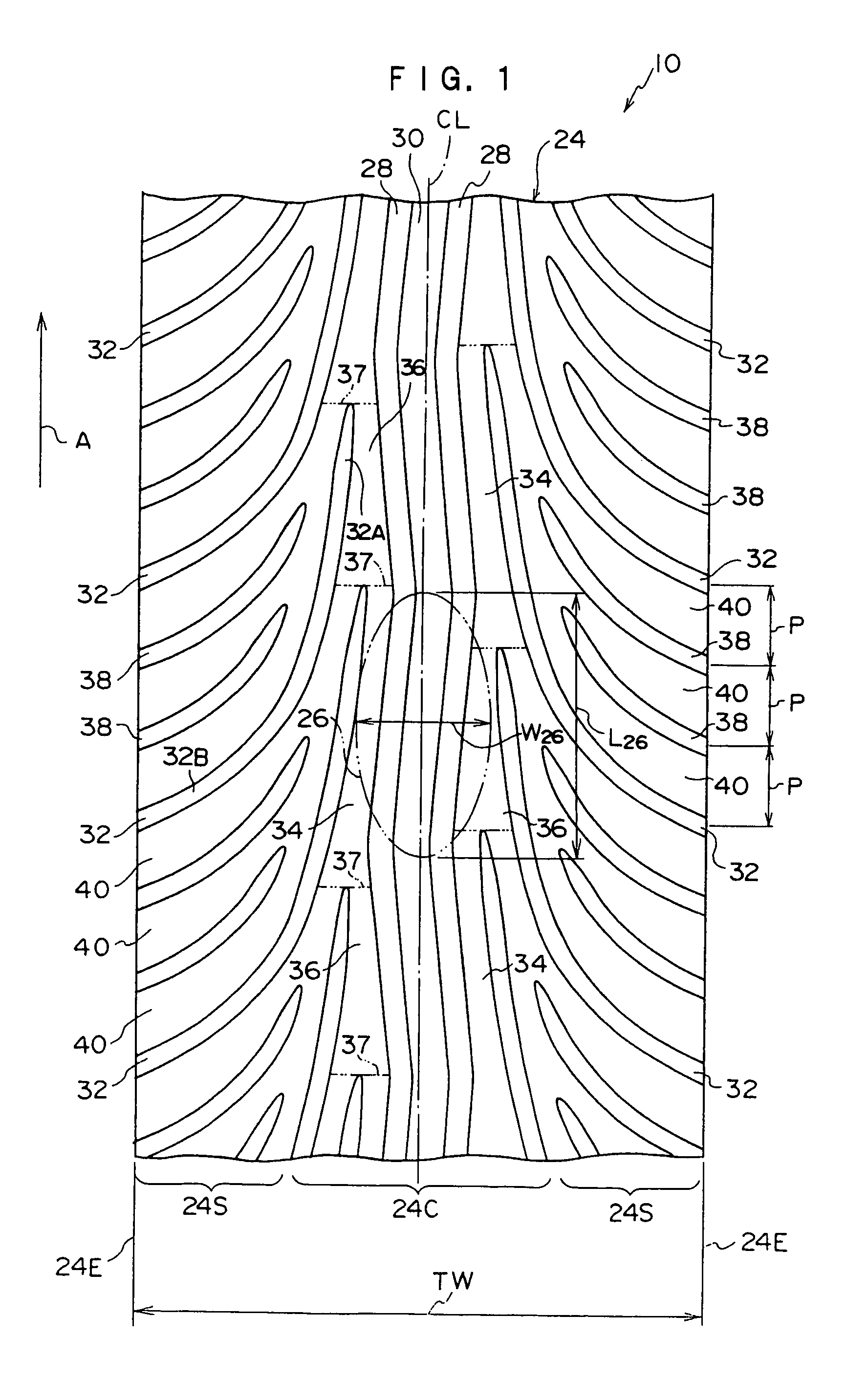
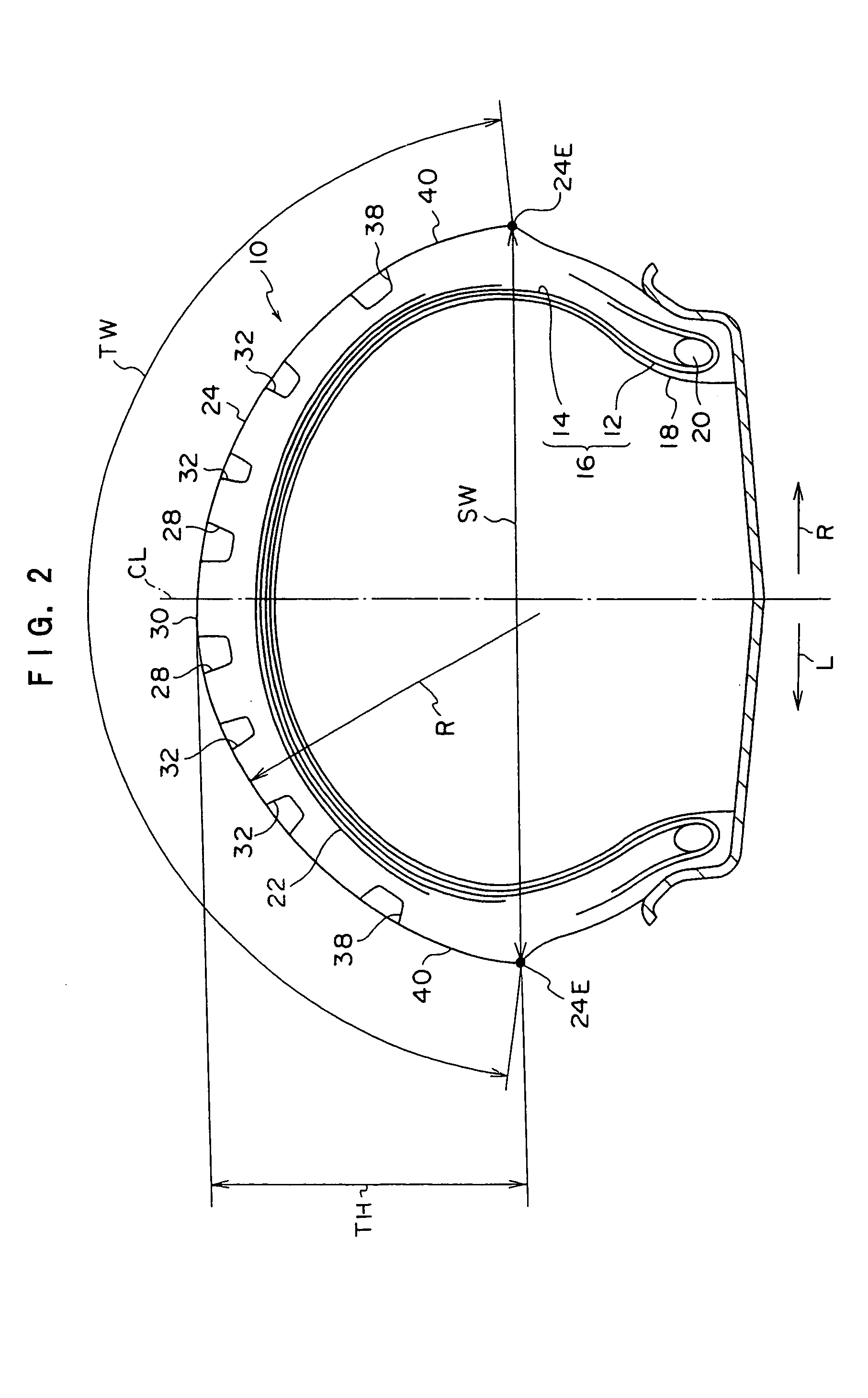
To provide a pneumatic tire for a motorcycle in which both wear resistance and wet steering stability can be attained. Since a pair of zigzag circumferential direction grooves 28 are positioned at the center of a tread central region 24C and has an amplitude, even when a certain camber angle is exceeded, an occurrence of a sudden separation of the zigzag circumferential direction groove 28 from a road-contact surface 26 can be prevented, whereby deterioration of wet steering stability can be suppressed. When the camber angle increases, water in a road-contact surface 26 is drained by inclining grooves 32 which are arranged at an external side of the zigzag circumferential direction groove 28. Since sharp inclining groove portions 32A of the inclining grooves 32 are positioned in the tread central region 24C, and no lug groove components are employed, circumferential direction rigidities of land portions in the tread central region 24C are high and exhibits excellent wear resistance. Since loose inclining groove portions 32B and sub-inclining grooves 38 of the inclining grooves 32 are positioned in tread side regions 24S, rigidities of land portions 40 resisting to inputs at the time of a large camber angle are high, and accordingly, wear resistance is high.

Description

BACKGROUND OF THE INVENTION[0001]1. Field of the Invention[0002]The present invention relates to a pneumatic tire for a motorcycle, and more particularly, to a pneumatic tire for a motorcycle in which both wear resistance and wet steering stability can be obtained.[0003]2. Background Art[0004]In order to obtain drainage performance during a motorcycle travel on a wet road surface, grooves are formed on a tread of a pneumatic tire for a motorcycle.[0005]For example, tread patterns shown in FIGS. 5 to 7 can respectively be employed as a tread pattern for a conventional pneumatic tire for a motorcycle.[0006]A tire 100 has tread pattern, shown in FIG. 5, which is a combination of small bock patterns from a viewpoint of drainage performance and a rubber with high elasticity. However, the tire 100 cannot provide effective block rigidity, and has not been suitable for a machine that outputs a large power in respect of wear resistance. In other words, when the tire 100 is used for a large p...

Claims


Application Information

Patent Timeline
Patent Type & Authority Patents(United States)
IPC IPC(8): B60C11/03B60C11/13B60C11/00B60C11/04B60C11/11
CPCB60C11/0302B60C11/0332B60C11/13B60C11/033B60C11/1323B60C2011/0374B60C2200/10B60C2011/0388B60C2011/0346
Inventor MIYASAKA, ATSUSHINAKAMURA, HAJIME
Owner BRIDGESTONE CORP
Learn More