Supercharge Your Innovation With Domain-Expert AI Agents!

Mounting apparatus for data storage device

a data storage device and mounting device technology, applied in the direction of electrical apparatus casings/cabinets/drawers, furniture parts, instruments, etc., can solve the problems of low efficiency, complicated assembly and disassembly thereof, unduly laborious and time-consuming, etc., to ensure the installation and removal of the data storage device.

Inactive Publication Date: 2007-10-02
HONG FU JIN PRECISION IND (SHENZHEN) CO LTD +1
View PDF10 Cites 13 Cited by
  • Summary
  • Abstract
  • Description
  • Claims
  • Application Information

AI Technical Summary

Benefits of technology

The present invention provides a mounting apparatus for securely installing and removing a data storage device to equipment such as a computer chassis. The apparatus includes a chassis, a drive bracket, and a locking device. The drive bracket is slidably attached to the chassis and has a joint plate with a confining hole and a baffle. The locking device has a sliding portion and an elastic patch for easy assembly and disassembly of the data storage device. The technical effect of this invention is to remind users the uninstalling direction and make the uninstallation quicker and easier.

Problems solved by technology

Fixing the drive bracket to the computer enclosure with bolts is unduly laborious and time-consuming: Furthermore, the computer enclosure needs extra operating space for carrying out the fixing operation.
Since components of a computer are compactly arranged in a computer enclosure, the assembly and disassembly thereof is complicated and low efficient.
Moreover, the components may be destroyed by inadvertent operation.
This leads to extra maintenance because of the plastic rails easily wearing out and resultantly needing replacement.
However, the assembly and disassembly of the drive bracket still need to be operated in inner space of a computer enclosure.

Method used


Image

  • Mounting apparatus for data storage device
  • Mounting apparatus for data storage device
  • Mounting apparatus for data storage device

Examples


Embodiment Construction

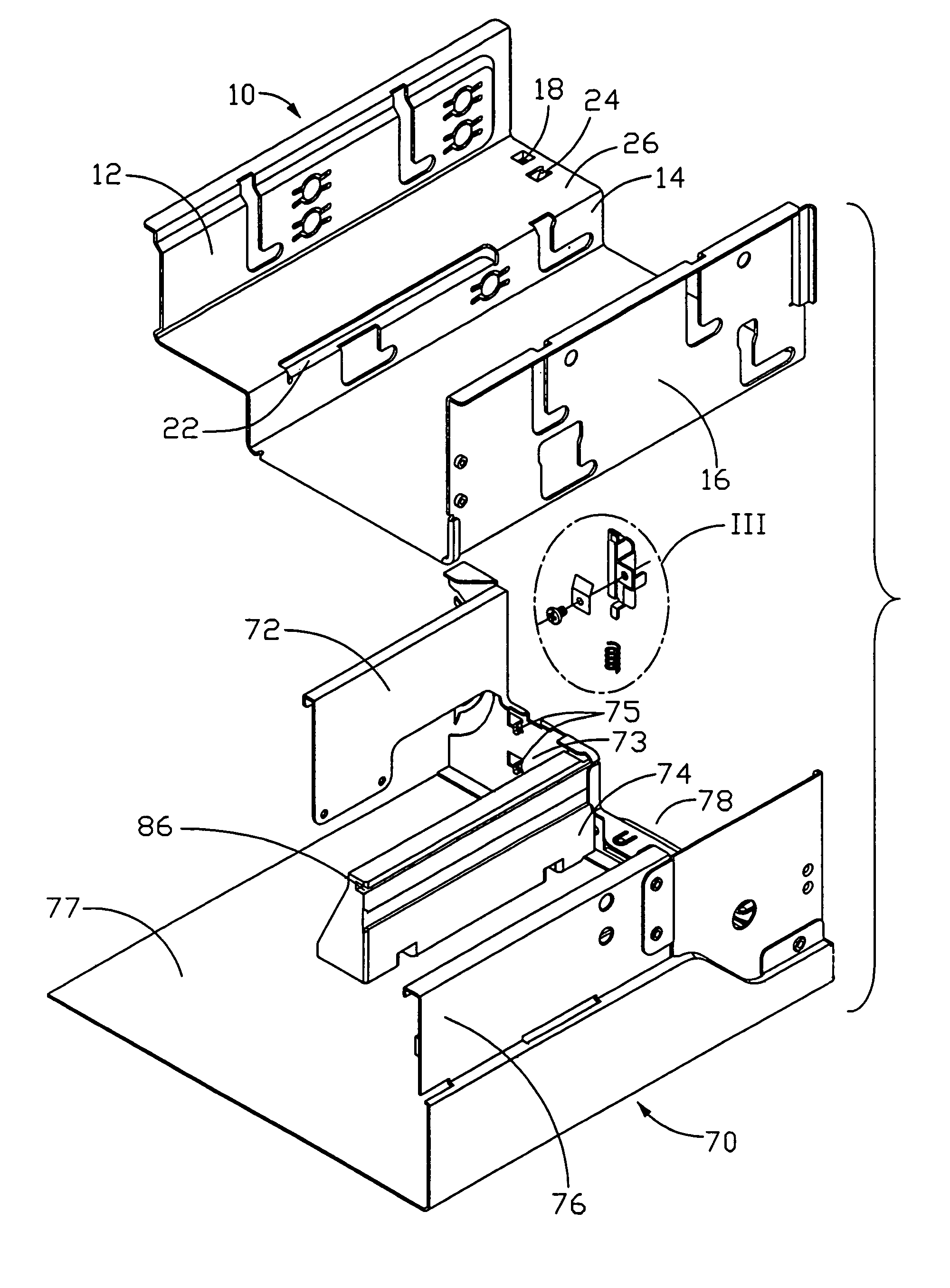
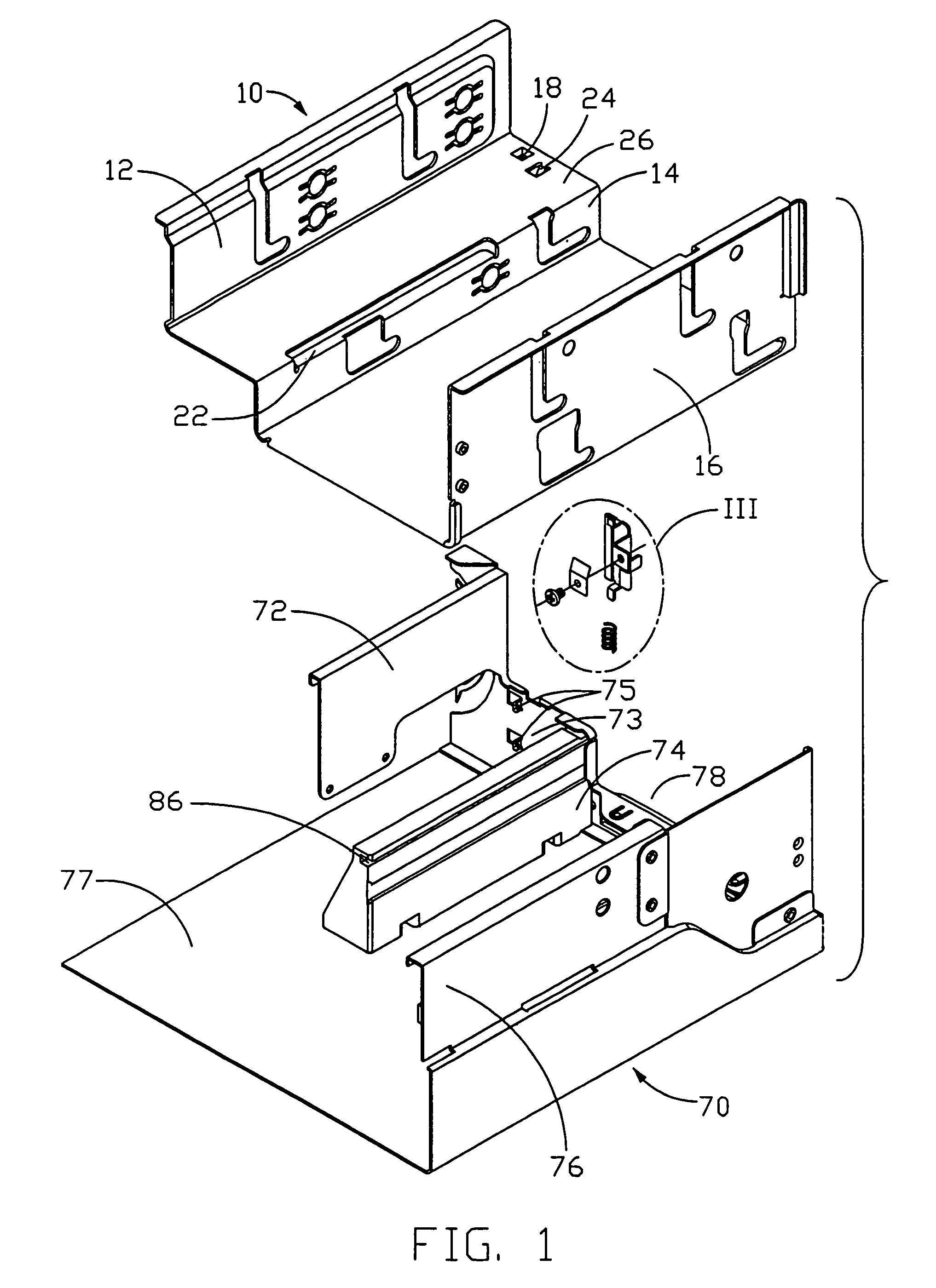
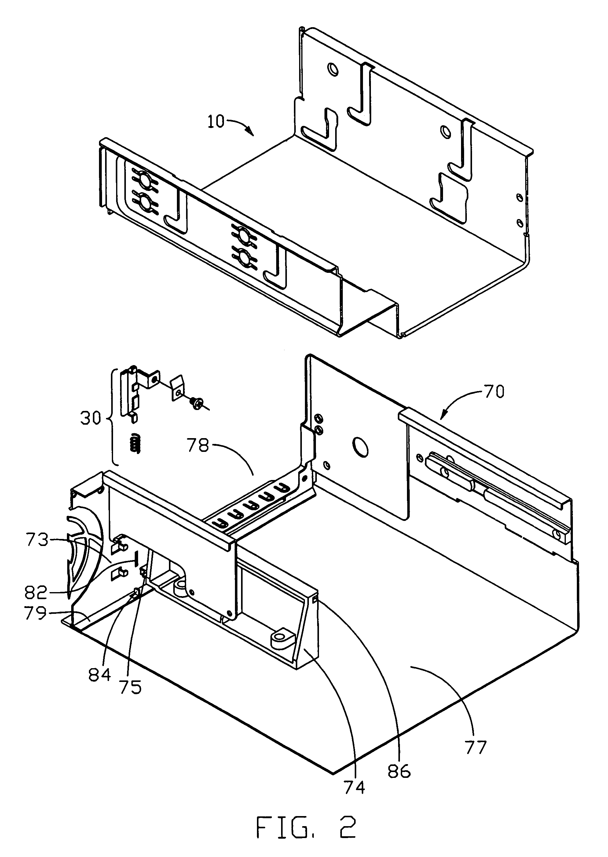
[0018]Referring to FIGS. 1, 2 and 3, a mounting apparatus for data storage devices (not shown) in accordance with the preferred embodiment of the invention, comprises a drive bracket 10, a locking device 30 and a chassis 70 of an electronic device like a computer. The drive bracket 10 is an integrative pane with ladder bend. The drive bracket 10 includes a first side wall 12, a second side wall 14 and a third side wall 16 which are all parallel to each other. There is a joint plate 26 between the first side wall 12 and the second side wall 14, on which defines a confining hole 18 and a downwardly baffle 24. The confining hole 18 is defined due to downwardly depressing of the joint plate 26 with each side is an inverse trapezium. A sliding slice 22 is stamped outwardly from the joint of the second side wall 14 and the joint plate 26.

[0019]The locking device 30 includes a sliding portion 32, an elastic patch 46, a spring 54 and a screw 56. The sliding portion 32 is approximately a rec...


PUM

PropertyMeasurementUnit
elasticaaaaaaaaaa
resilientaaaaaaaaaa
resilient forceaaaaaaaaaa

Abstract

A mounting apparatus for drive bracket comprises a chassis (70) forming a front plate (73), a drive bracket (10) mounted on the chassis and a locking device (30). The drive bracket comprises a joint plate (26), and the joint plate comprises a confining hole (18) and a baffle (24) therein. The locking device comprises a sliding portion (32) slidably mounted to the front plate and an elastic patch (46) arranged on the sliding portion, a confining patch (34) is attached to the upper edge of the sliding portion and a locking patch (44) extends downwardly from the bottom edge of the sliding portion. When assembling, the drive bracket stays in the chassis, the confining patch is engaging in the confining hole, the elastic patch presses the baffle; when disassembling the drive bracket is pushed outwardly by the elastic patch pressing the baffle.

Description

BACKGROUND OF THE INVENTION[0001]1. Field of the Invention[0002]The present invention relates to mounting apparatus, and particularly to a mounting apparatus for steadily and securely mounting a data storage device therein.[0003]2. Description of the Related Art[0004]Generally speaking, when a computer is assembled, a drive bracket is mounted in a computer enclosure, and then data storage devices are fixed to the drive bracket. The data storage devices comprise various combinations of hard disk drives (HDDs), floppy disk drives (FDDs), and compact disk-read only memory (CD-ROM) drives.[0005]A conventional drive bracket is generally attached to a computer enclosure by bolts or rails. Fixing the drive bracket to the computer enclosure with bolts is unduly laborious and time-consuming: Furthermore, the computer enclosure needs extra operating space for carrying out the fixing operation. Since components of a computer are compactly arranged in a computer enclosure, the assembly and disa...

Claims


Application Information

Patent Timeline
Patent Type & Authority Patents(United States)
IPC IPC(8): H05K5/00A47B81/00G06F1/16G06F1/18G06F7/12G11B33/12H05K7/00
CPCG06F1/181G11B33/128G06F1/187G06F1/184
Inventor CHEN, YUN-LUNGDING, LIN
Owner HONG FU JIN PRECISION IND (SHENZHEN) CO LTD
Features
  • R&D
  • Intellectual Property
  • Life Sciences
  • Materials
  • Tech Scout
  • Unparalleled Data Quality
  • Higher Quality Content
  • 60% Fewer Hallucinations
Learn More