Supercharge Your Innovation With Domain-Expert AI Agents!

CPU mounting apparatus

a technology for mounting apparatuses and cpues, which is applied in the direction of electrical apparatus contruction details, coupling device connections, instruments, etc., can solve the problems of inconvenient and laborious handwork to insert the cpu into the socket, pins b>120/b>′ being often damaged or bent,

Inactive Publication Date: 2006-02-16
HONG FU JIN PRECISION IND (SHENZHEN) CO LTD +1
View PDF4 Cites 4 Cited by
  • Summary
  • Abstract
  • Description
  • Claims
  • Application Information

AI Technical Summary

Benefits of technology

[0003] The present invention relates to mounting apparatus for CPUs, and particularly to a mounting apparatus for readily and securely installing or removing a CPU to or from a socket.

Problems solved by technology

However, some of the pins 120′ are often damaged or bent when too much force is applied thereon or the force is inequality during forced manipulation.
Moreover, it is rather inconvenient and laborious to insert the CPU into the socket by handwork.

Method used


Image

  • CPU mounting apparatus
  • CPU mounting apparatus
  • CPU mounting apparatus

Examples


Embodiment Construction

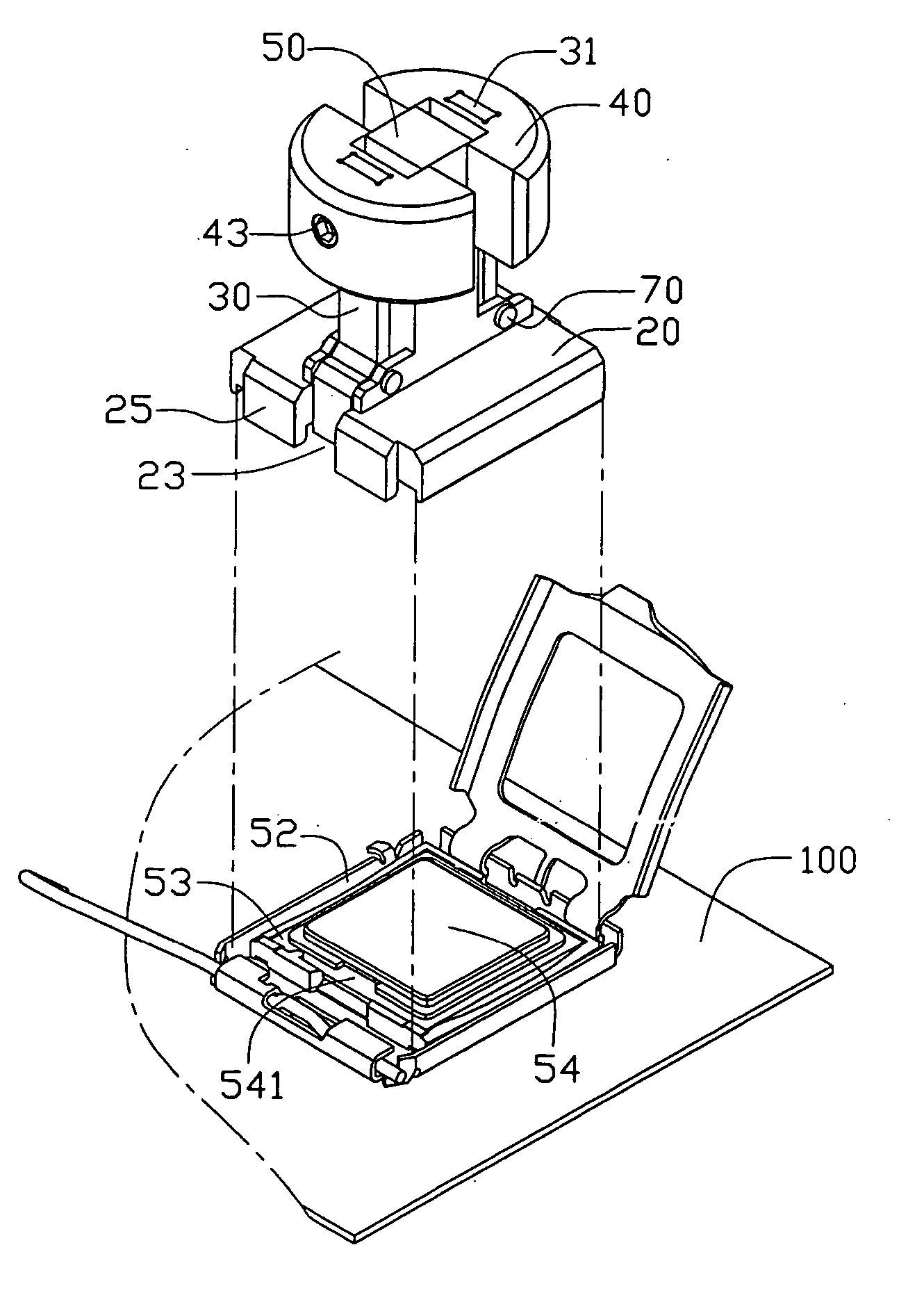
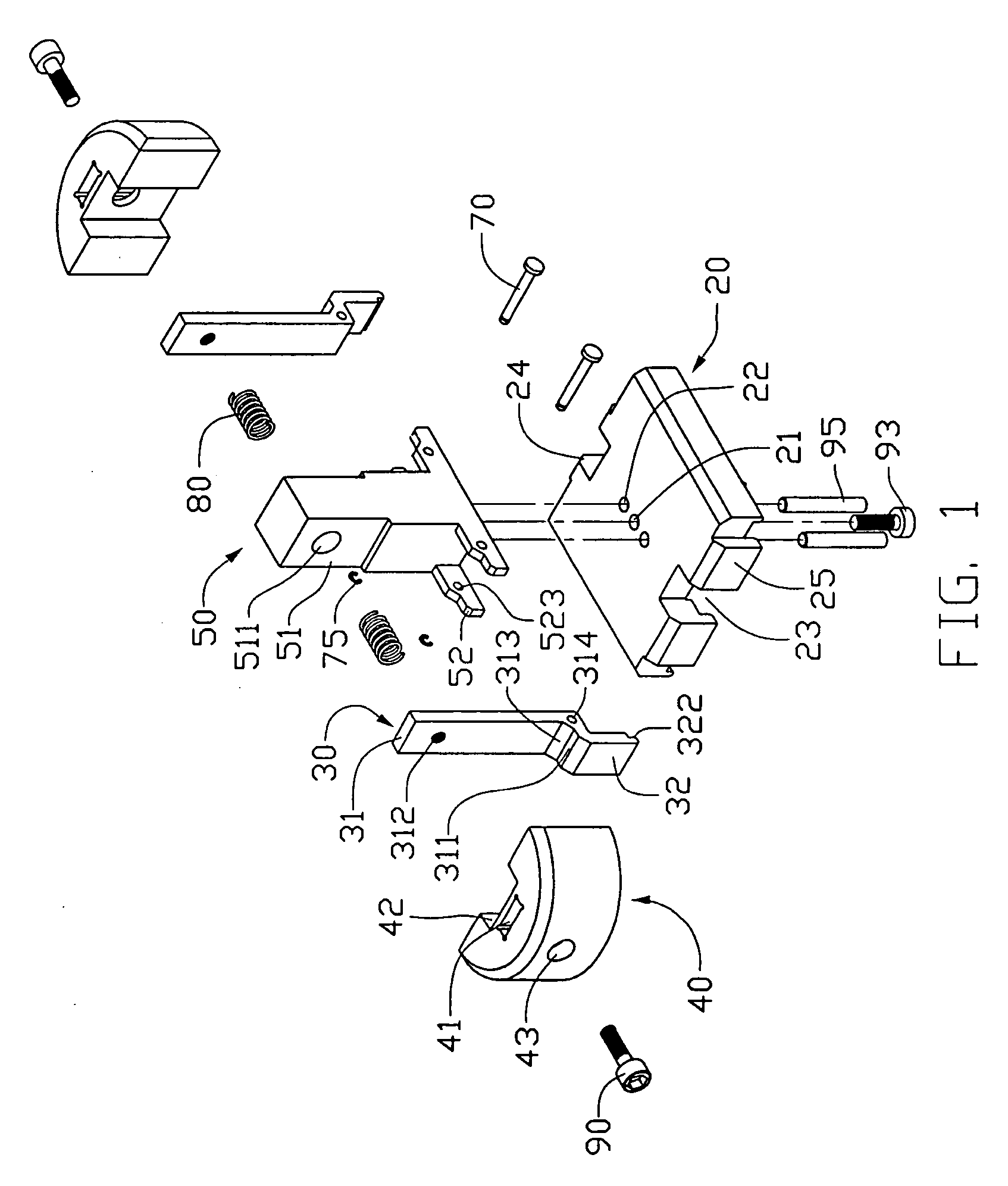
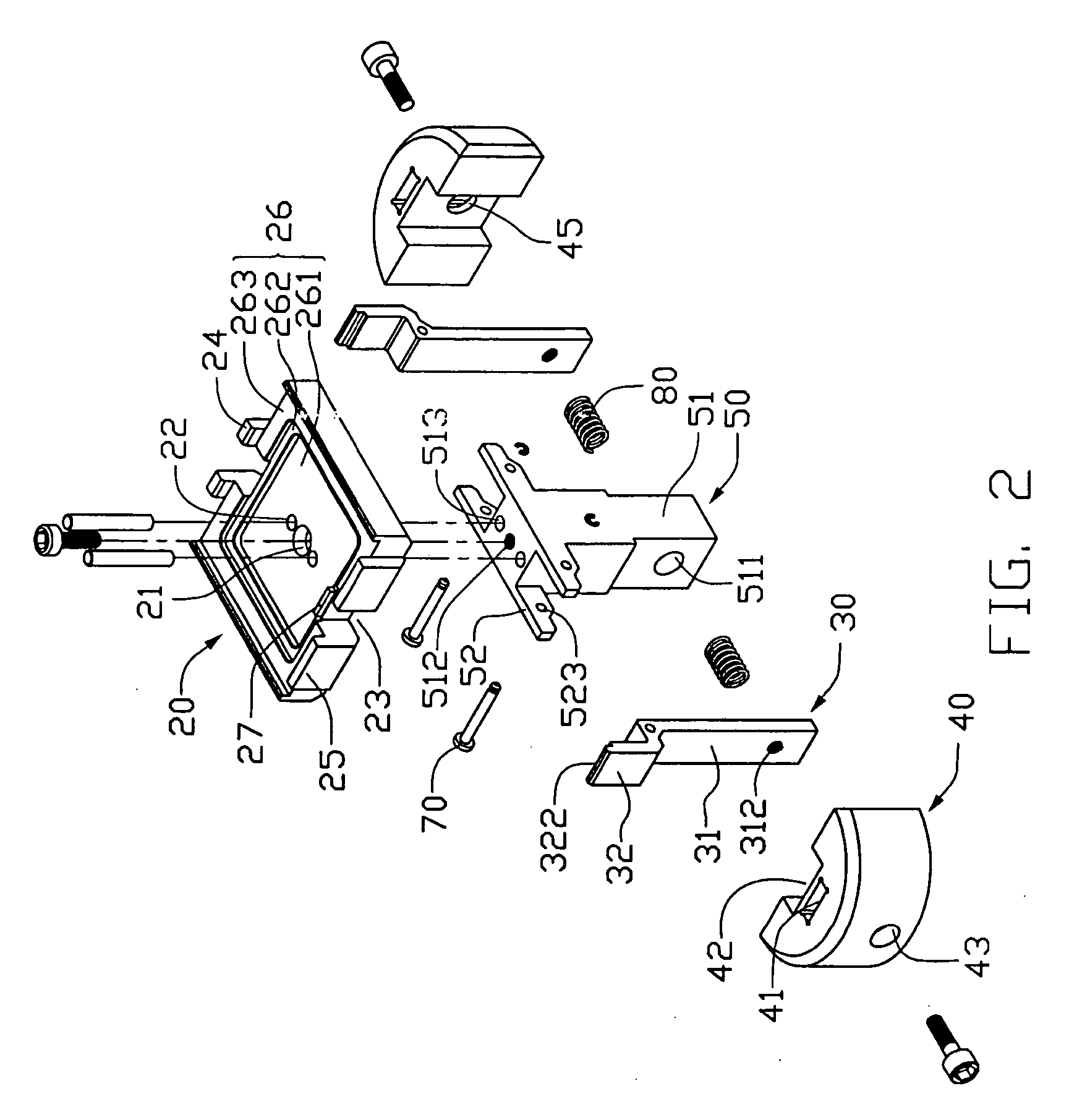
[0014] Referring to FIGS. 1, 2 and 3, a CPU mounting apparatus in accordance with a preferred embodiment of the present invention is shown for mounting a CPU 53 to a socket 52 on a motherboard 100. The CPU mounting apparatus includes a base 20, a fixing member 50, a pair of clipping members 30, a pair of operation members 40 and a pair of resilient members 80.

[0015] The base 20 has a concave 26 in a bottom thereof. The concave 26 having a stepped shape includes an inner concave 261, a middle concave 262 and an outer concave 263. A stepped heat sink 54 arranged on a top of the CPU 53 can be held in the inner concave 261 and the middle concave 262. The CPU 53 can be held in the outer concave 263. A pair of first cutouts 23 is defined in two opposite sides of the base 20 respectively. A protrusion 27 protrudes from the middle concave 262 in one cutout 23. The protrusion 27 has a height equal to a height between the middle concave 262 and the outer concave 263. The protrusion 27 and a ...


PUM


Abstract

A mounting apparatus to mount a CPU (53) to a socket (52) includes a base (20), a fixing member (50), a pair of clipping members (30), a pair of operation members (40) and a pair of resilient members (80). The base defines a concave (26) adapted to accommodate the CPU therein. The fixing member is arranged on a top of the base. Each clipping member includes a rotatable portion (313) respectively pivotably mounted to two opposite sides of a lower portion of the fixing member. Each clipping member includes a fixing portion (31) and a clipping portion (32) located at opposite sides of the rotatable portion respectively. A hook (322) extends downwardly from the clipping portion for hooking the CPU. The operation members are mounted to the fixing portions of the fixing member. Each of the resilient members is located between the fixing member and a corresponding operation member.

Description

CROSS-REFERENCE TO RELATED APPLICATIONS [0001] Relevant subject matter is disclosed in two co-pending U.S. Patent Applications entitled “CPU mounting apparatus”, respectively file in Nov. 16, 2004 with the application Ser. No. 10 / 989,700, and Apr. 13, 2005 with the application Ser. No. 11 / 105,208, assigned to the same assignee with this application.BACKGROUND OF THE INVENTION [0002] 1. Field of the Invention [0003] The present invention relates to mounting apparatus for CPUs, and particularly to a mounting apparatus for readily and securely installing or removing a CPU to or from a socket. [0004] 2. General Background [0005] Conventionally, a central processing unit (CPU) is inserted into a socket connector directly. Referring to FIGS. 6 and 7, a socket 12′ of an Intel Pentium 5 CPU 13′ is mounted on a motherboard 1′. The socket 12′ includes a plurality of pins 120′ and two slots 121′, 123′ in two sides thereof for readily mounting the CPU 13′. The CPU 13′ has a plurality of pads 13...

Claims


Application Information

Patent Timeline
Patent Type & Authority Applications(United States)
IPC IPC(8): H05K7/20G06F1/16H05K7/10
CPCY10S439/94H05K7/1053
Inventor LUO, YONG-MIN
Owner HONG FU JIN PRECISION IND (SHENZHEN) CO LTD
Features
  • R&D
  • Intellectual Property
  • Life Sciences
  • Materials
  • Tech Scout
  • Unparalleled Data Quality
  • Higher Quality Content
  • 60% Fewer Hallucinations
Learn More