Adjustable prying bar

a technology of adjustable bar and prying bar, which is applied in the direction of crowbars, lifting devices, wrenches, etc., can solve the problems of not being able to make the object a little higher, prying an object, and causing great inconvenience to users

Inactive Publication Date: 2007-10-09
CHANG PI HSIA
View PDF13 Cites 52 Cited by
  • Summary
  • Abstract
  • Description
  • Claims
  • Application Information

AI Technical Summary

Problems solved by technology

So that it could only pry an object to a predetermined height and couldn't make the object a little higher.
So it causes great inconvenience to the user.

Method used


Image

  • Adjustable prying bar
  • Adjustable prying bar
  • Adjustable prying bar

Examples


Embodiment Construction

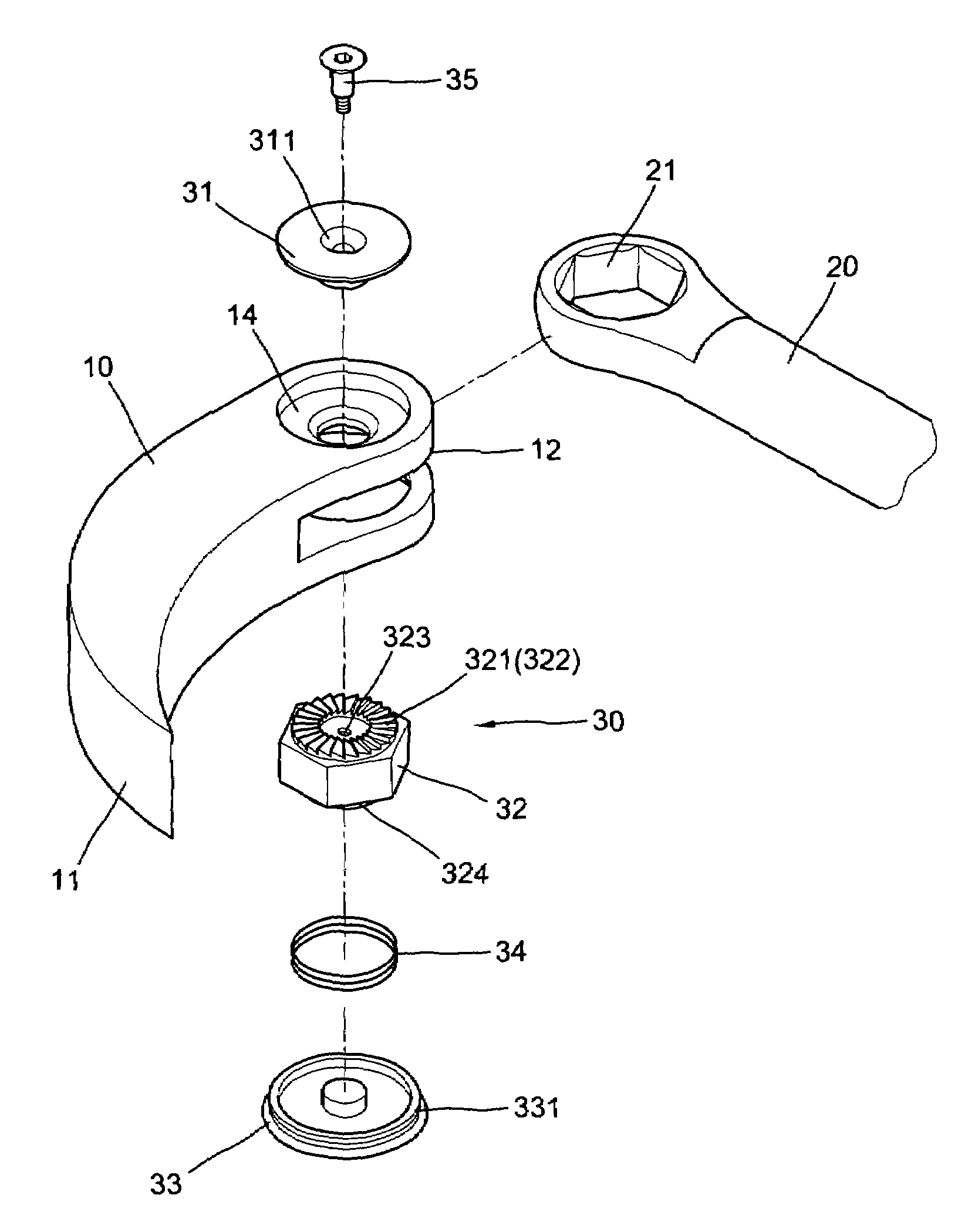
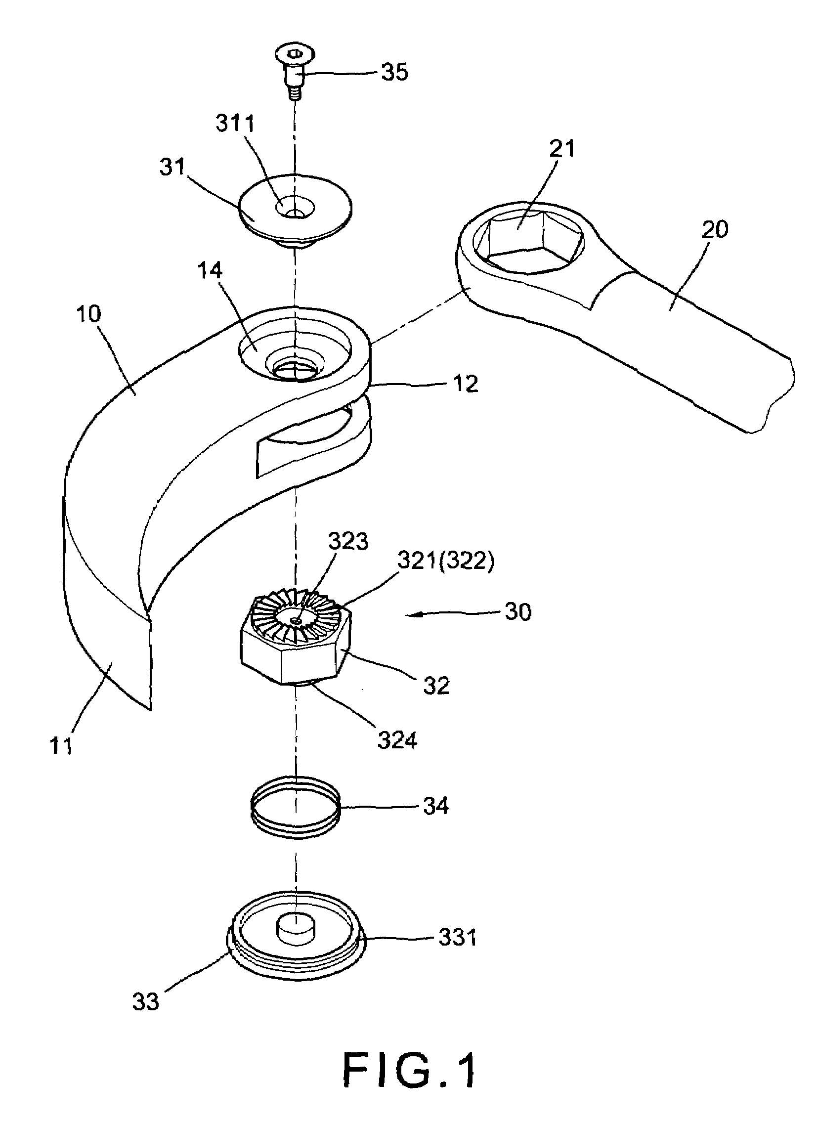
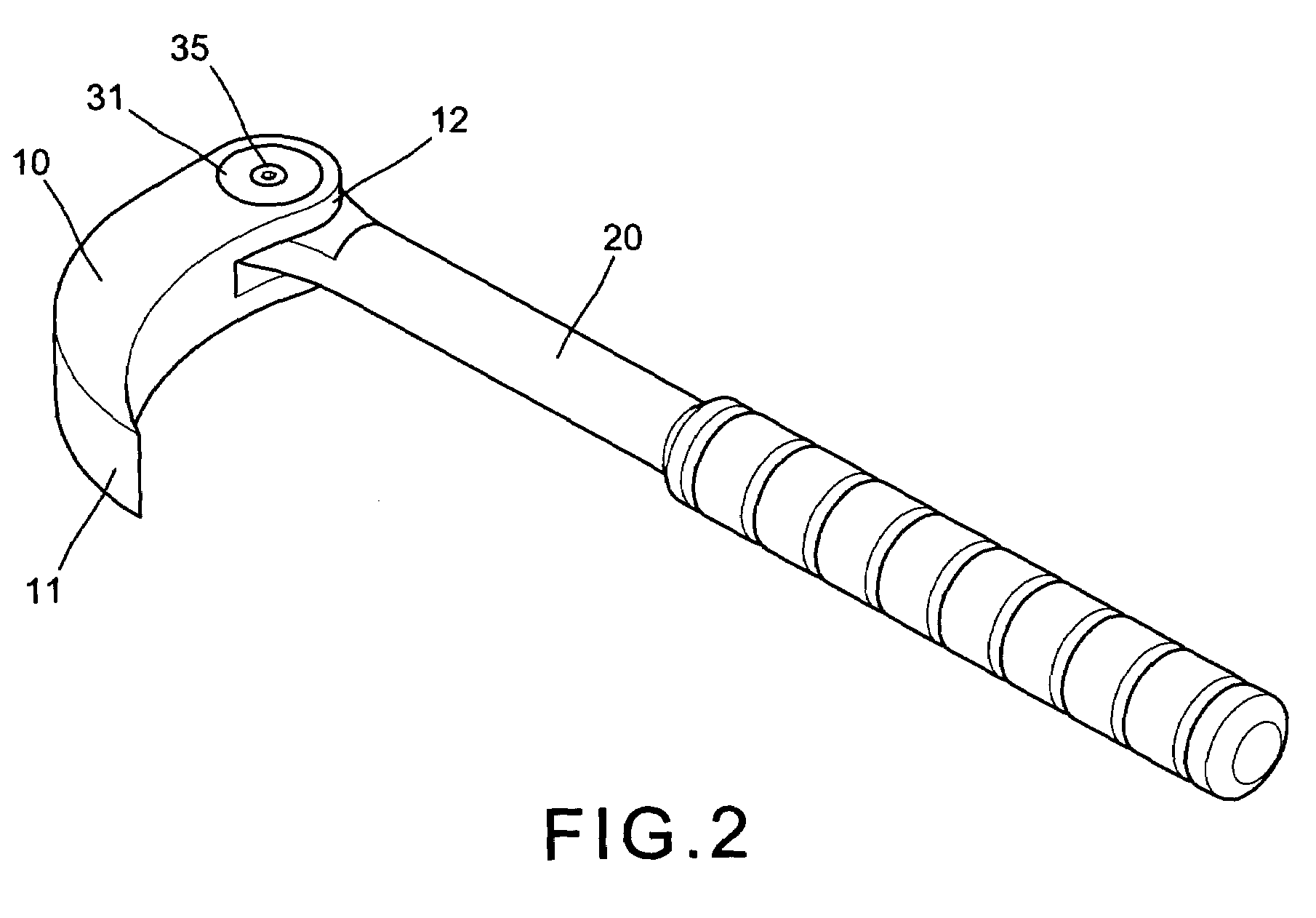
[0012]With reference to the drawings and initiated from FIGS. 1 to 3, the prying bar of the present invention comprises generally a prying head 10, a handle 20 and a checking mechanism 30.

[0013]The prying head has an arcuate body, a flat tipped lower end 11 and a lug 12 at upper end, wherein the lug 12 has a circular depression 14 with a central bore in the top of upper portion, a internal stop ring 13 on opposite side of the depression 14, the internal stop ring 13 has a plurality of radially inverse teeth 131 therearound, a large aligned through hole in the lower portion of the lug 12 having inner threads around inner periphery.

[0014]The handle 20 has a hexagon hole 21 in the flat front end engaged within the lug 12 of the prying head 10 therebetween.

[0015]The checking mechanism 30 comprises an upper cover 31 engaged within the circular depression 14 of the lug 12 including a central bore 311, a screw 35 inserted through the central bore 311 of the upper cover 31 and engaged with ...


PUM


Abstract

An adjustable prying bar includes a prying head having an arcuate body, a flat tipped lower end a lug at upper end wherein the lug has a circular depression and an inverse stop ring on upper portion and inner thread on lower portion, a handle rotatably engaged with the upper end of the prying head having flat front end with a hexagon hole therein engaged within the lug of the prying head, and a checking mechanism including an upper cover, a lower cover, a hexagon plate and a spring separately engaged with the lug and the hexagon hole of the handle wherein the hexagon plate has a stop ring engageable with stop ring of the lug. Thereby, the angle between the prying head and the handle enables to adjust for larger or smaller than 90 degrees.

Description

BACKGROUND OF THE INVENTION[0001]The present invention relates to the prying tools and more particularly to an adjustable prying bar which has an upper and lower portions rotatably engaged with each other so as to pry the working object to a highest extent.[0002]As we know, a prying bar can be use to automobile maintenance and / or to pry variety of objects. Conventional prying bar has a prying head perpendicularly and solidly connected to a handle to form an angle about 90 degrees, and couldn't make angular adjustment. So that it could only pry an object to a predetermined height and couldn't make the object a little higher. Sometimes it even couldn't pry up the object. So it causes great inconvenience to the user.SUMMARY OF THE PRESENT INVENTION[0003]The present invention has a main object to provide an adjustable prying bar which has upper and lower checking devices capable of rotating the handle to a more large angle in order to pry the working object up to a required height.[0004...

Claims


Application Information

Patent Timeline
Patent Type & Authority Patents(United States)
IPC IPC(8): B25C11/00B66F15/00
CPCB66F15/00
Inventor CHANG, PI-HSIA
Owner CHANG PI HSIA
Why Eureka
Try Eureka