Expansion valve control system and method and refrigeration unit employing the same

Active Publication Date: 2007-11-06
HEATCRAFT REFRIGERATION PRODS
View PDF4 Cites 25 Cited by
  • Summary
  • Abstract
  • Description
  • Claims
  • Application Information

AI Technical Summary

Benefits of technology

[0007]The present invention allows optimal control of a refrigeration system expansion valve during various operating conditions. Advantageously, repositioning of the expansion valve is proportional to the superheat error. When operating under heavy load conditions, such as, an initial temperature pull-down or following a defrost cycle, the present invention rapidly increases the expansion valve position in response to high values of superheat. As the load decreases over time, the expansion valve position responds by gradually decreasing.
[0008]When operating under nor

Problems solved by technology

Advantageously, repositioning of the expansion

Method used


Image

  • Expansion valve control system and method and refrigeration unit employing the same
  • Expansion valve control system and method and refrigeration unit employing the same
  • Expansion valve control system and method and refrigeration unit employing the same

Examples


Example

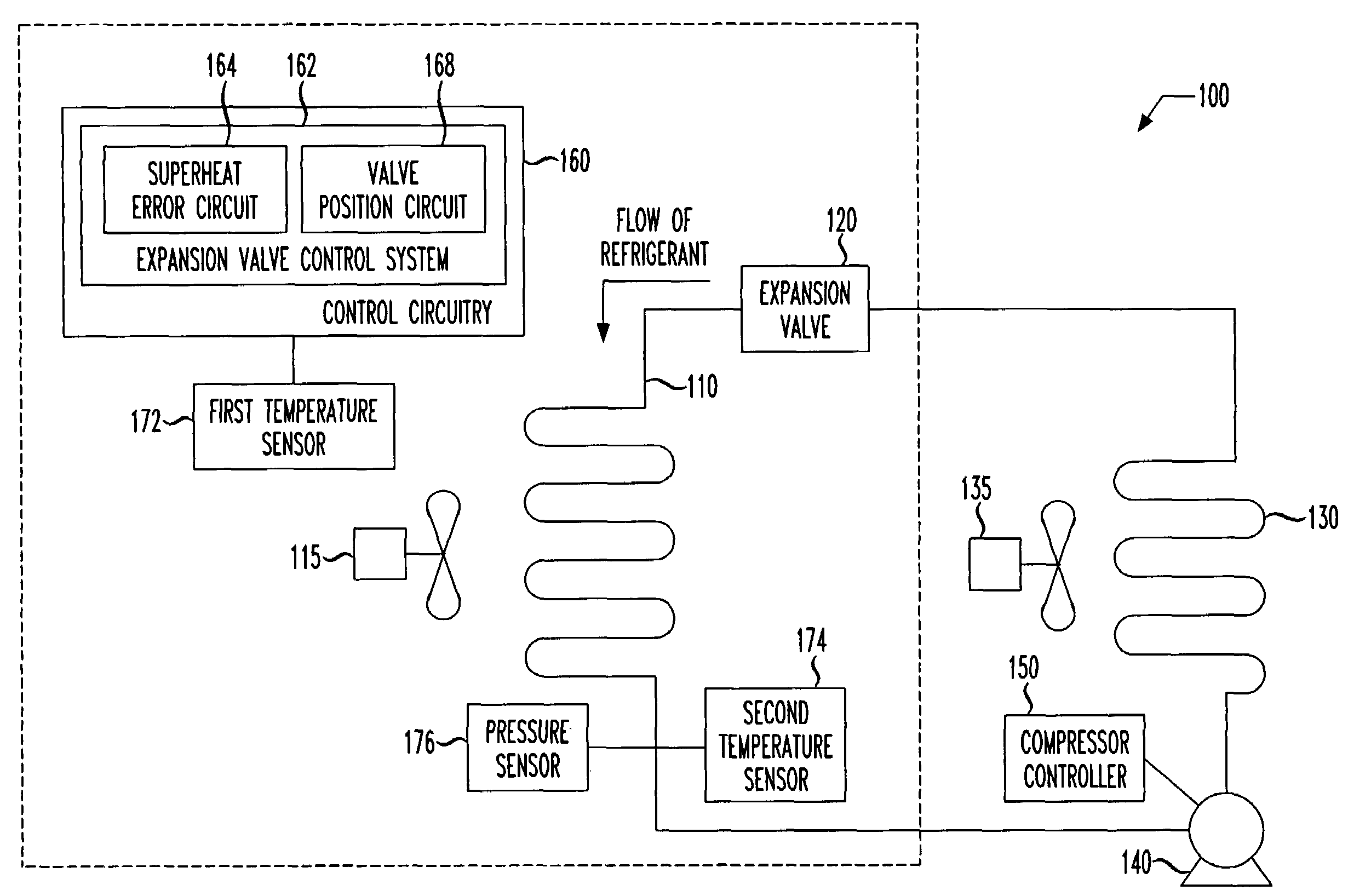
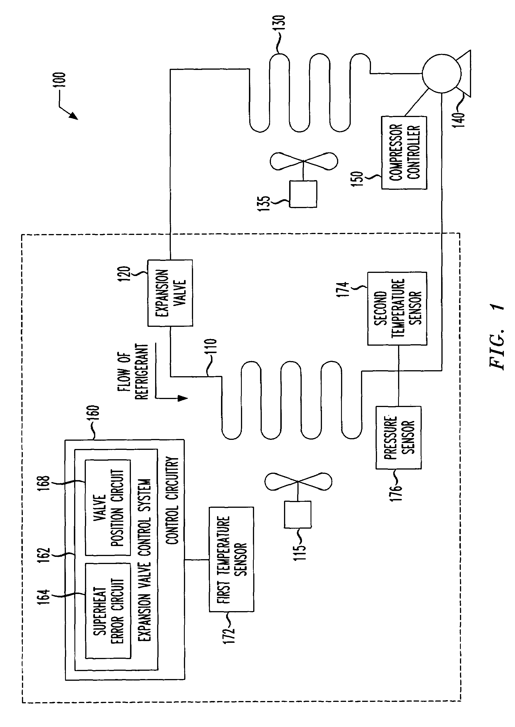
[0018]Referring initially to FIG. 1, illustrated is a block diagram of a refrigeration unit, generally designated 100, constructed in accordance with the principles of the present invention. The refrigeration unit 100 includes an evaporator 110, an evaporator fan 115, an expansion valve 120, a condenser 130, a condenser fan 135, a compressor 140, a compressor controller 150 and control circuitry 160 including an expansion valve control system 162. The refrigeration unit 100 also has control sensors including a first temperature sensor 172, a second temperature sensor 174 and a pressure sensor 176. Components of the refrigeration unit 100 that are typically located inside are indicated within the dashed line of FIG. 1. Inside may be within a cooling space or within a space associated with the cooling space. One skilled in the art will understand that the refrigeration unit 100 may include additional components that are commonly employed within conventional refrigeration units that ar...


PUM


Abstract

An expansion valve control system, a method of controlling an expansion valve and a refrigeration unit incorporating the same. In one embodiment, the expansion valve control system includes (1) a superheat error circuit configured to derive a superheat error for a fluid associated with the expansion valve and (2) a valve position circuit, associated with the superheat error circuit, configured to reposition the expansion valve proportionally based on both a current position thereof and the superheat error.

Description

TECHNICAL FIELD OF THE INVENTION[0001]The present invention is directed, in general, to air conditioning and refrigeration systems and, more specifically, to an expansion valve control system and method and refrigeration unit employing the same.BACKGROUND OF THE INVENTION[0002]Refrigeration systems usually include an evaporator, a condenser, a compressor, an expansion valve and a controller. Typically, in a residential air conditioning system, the evaporator and controller is located inside, the condenser and compressor are located outside and the expansion valve is located inside between an outlet of the condenser and an inlet of the evaporator. The expansion valve regulates the flow rate of a refrigerant through the evaporator to obtain a desired temperature in a space to be cooled, or cooling space.[0003]The controller can be programmed to control operation of the refrigeration system based on inputs from various temperature and pressure sensors to obtain the desired temperature ...

Claims


Application Information

Patent Timeline
IPC IPC(8): F25B41/04
CPCF25B41/062F25B2600/21F25B2700/21175F25B2700/197F25B2700/2104F25B2600/2513F25B41/35Y02B30/70
Inventor BAILEY, PATRICK M.
Owner HEATCRAFT REFRIGERATION PRODS
Why Eureka
Try Eureka