Cosmetics discharge structure of cosmetics case

a cosmetics case and structure technology, applied in the field of cosmetics case discharge structure, can solve the problems of cosmetics case bad keeping, cosmetics case leakage, inner and outer moving bodies that are compressed by compressing and releasing inner and outer moving bodies cannot recover, etc., to reduce the assembly processing of cosmetics case, reduce production cost, and facilitate mold manufacturing

Inactive Publication Date: 2007-11-20
BYUN YOUNG KWANG
View PDF12 Cites 21 Cited by
  • Summary
  • Abstract
  • Description
  • Claims
  • Application Information

AI Technical Summary

Benefits of technology

[0008]In order to solve a problem above-described, through pressing repeatedly bottom part of inner moving body that is composing to a cosmetics case, a cone type elastic part and a spring that formed in the middle member can be control freely discharge and interception of cosmetics by compressing and an middle member that composed to a liquid transfer passage, a cone type elastic part, a coupling member, and an opening valve is formed to one form, is easy to manufacture mold and reduces producing cost by decreasing a assembly processing of a cosmetics case of a present invention. Also, assembly and dismantling of an inner moving body and a coupling member are easy and an inner moving body separates and opens to add cosmetics that can be possible to refill when a cosmetics including an inner moving body is exhausted.
[0011]A cosmetics including in the receiving part 11 moves to a inner space part 24a formed to a cone type elastic part 24 through a opening hole 28 by compressing a receiving part and rising an inner moving body 10, a vertical rod 27 rises and an inner hole 22 opens by rising an inner moving body 10 to a top, moved cosmetics in an inner space part 24a discharges to a brush 43 through a liquid discharger 42 from the inner hole 22 and releases pushing power to an inner moving body 10, an inner moving body 10 declines and returns by an expansion of a cone type elastic part 24 formed to the middle member 20 and elastic and repellent force of a spring 41, a vertical rod 27 declines and seals an inner hole 22, closed opening hole 28 opens and a cosmetics including a receiving part 11 will not discharge to a brush 43, an inner hole 22 and an opening hole 28 open by pressing and releasing inner moving body 10 and a cone type elastic part 24 and a spring 41 that formed in the middle member 20 can be control freely discharge and interception of cosmetics by compressing.
[0012]Also, a middle member 20 that composed to a liquid transfer passage 21, a cone type elastic part 24, a coupling member 25, and an opening valve 23 is formed to one form, is easy to manufacture mold and reduces producing cost by decreasing a assembly processing of a cosmetics case 1 of a present invention.
[0013]Also, assembly and dismantling of an inner moving body 10 and a coupling member 25 are easy and an inner moving body separates and opens to add cosmetics that can be possible to refill when a cosmetics including an inner moving body 10 is exhausted.

Problems solved by technology

A cosmetic that was in a inner part of a tube type case by compressing and releasing a tube type case discharged to a cosmetics brush to make up but the cosmetics case had a problem that is bad to keep because a cosmetics often leaked unnecessary.
However, if the cosmetics case repeats movements that discharge cosmetics of powder type or liquid type, inner and outer moving body that compressed by compressing and releasing inner and outer moving bodies can not recover.
There is a disadvantage that makes dirty and damage to surround by leaking cosmetics in case of keeping careless.
There is a disadvantage that producing cost will be increase by many processing of assembling manufacturing.

Method used


Image

  • Cosmetics discharge structure of cosmetics case
  • Cosmetics discharge structure of cosmetics case
  • Cosmetics discharge structure of cosmetics case

Examples


Embodiment Construction

[0021]Hereinafter, preferred embodiments of the present invention will be described with reference to the accompanying drawings.

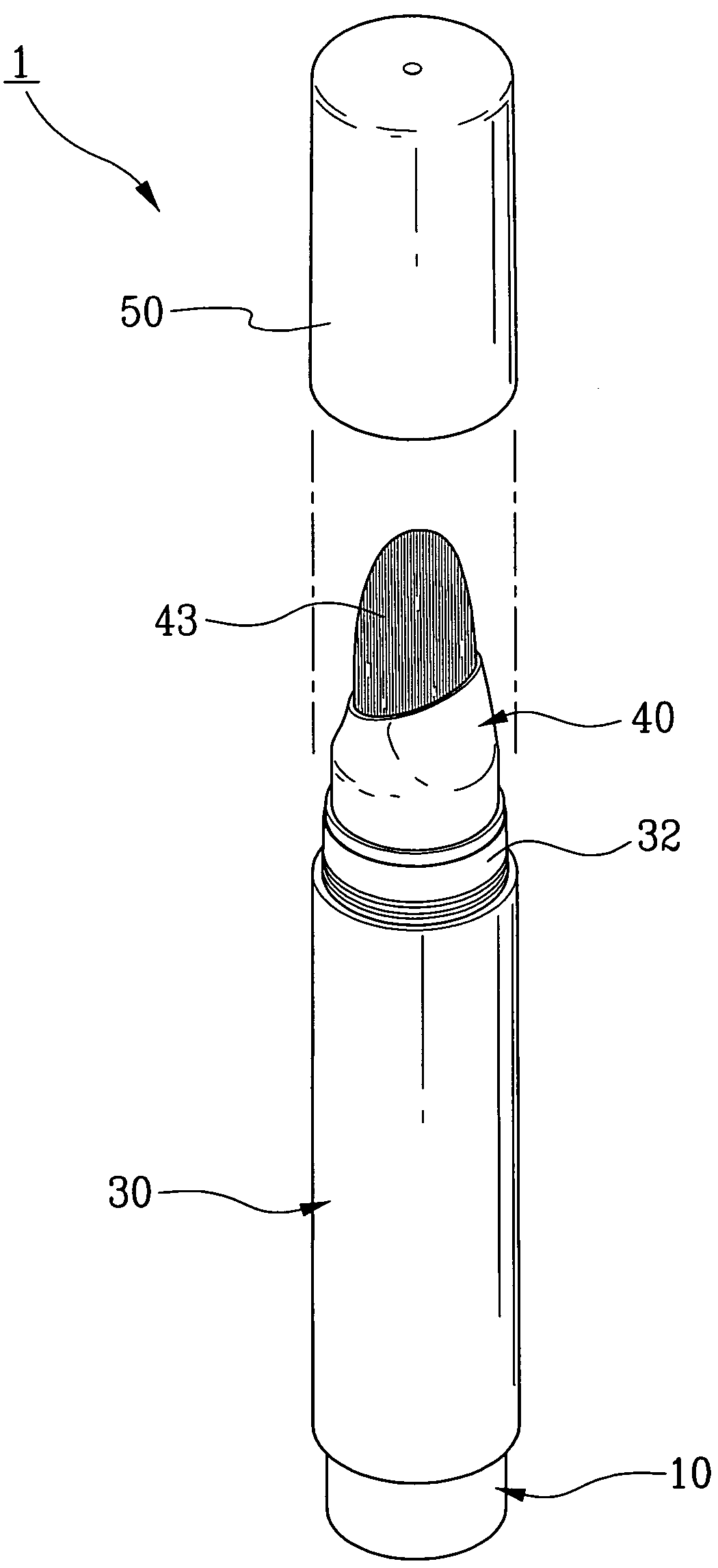
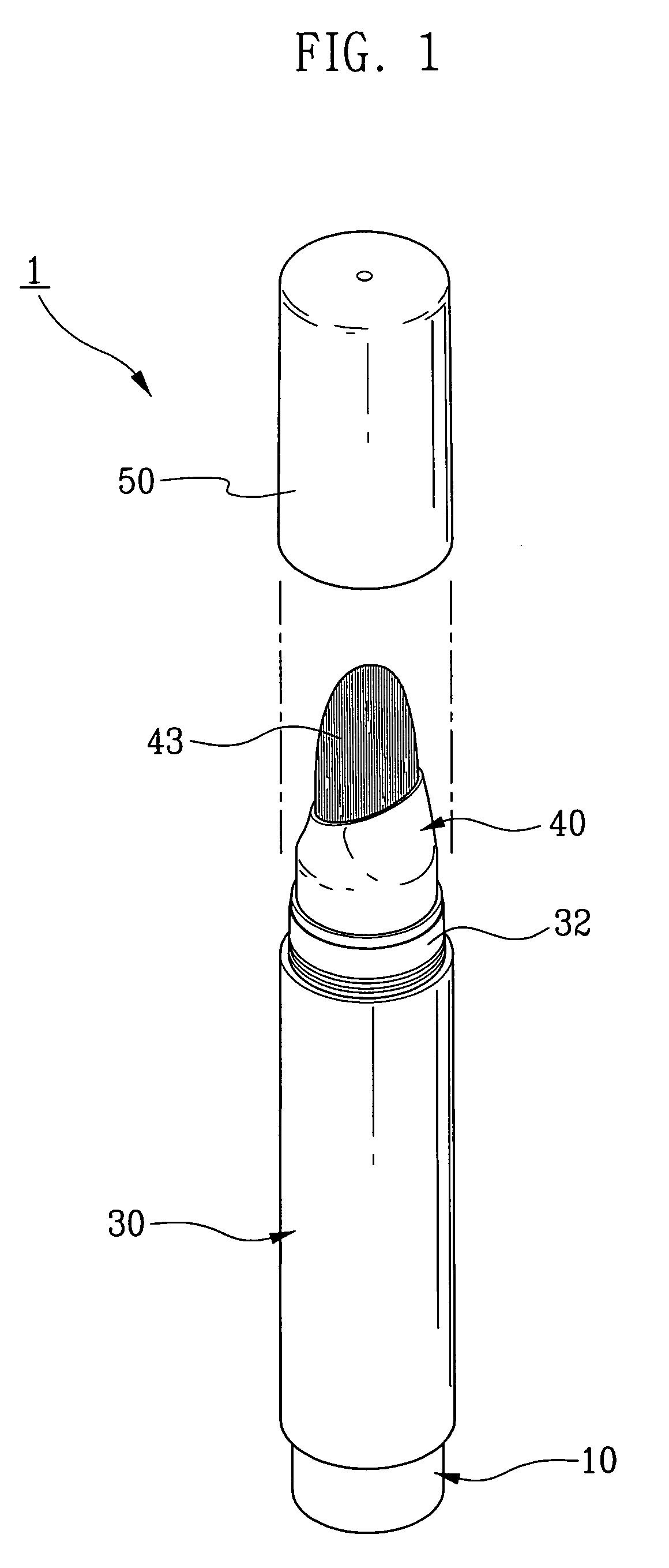
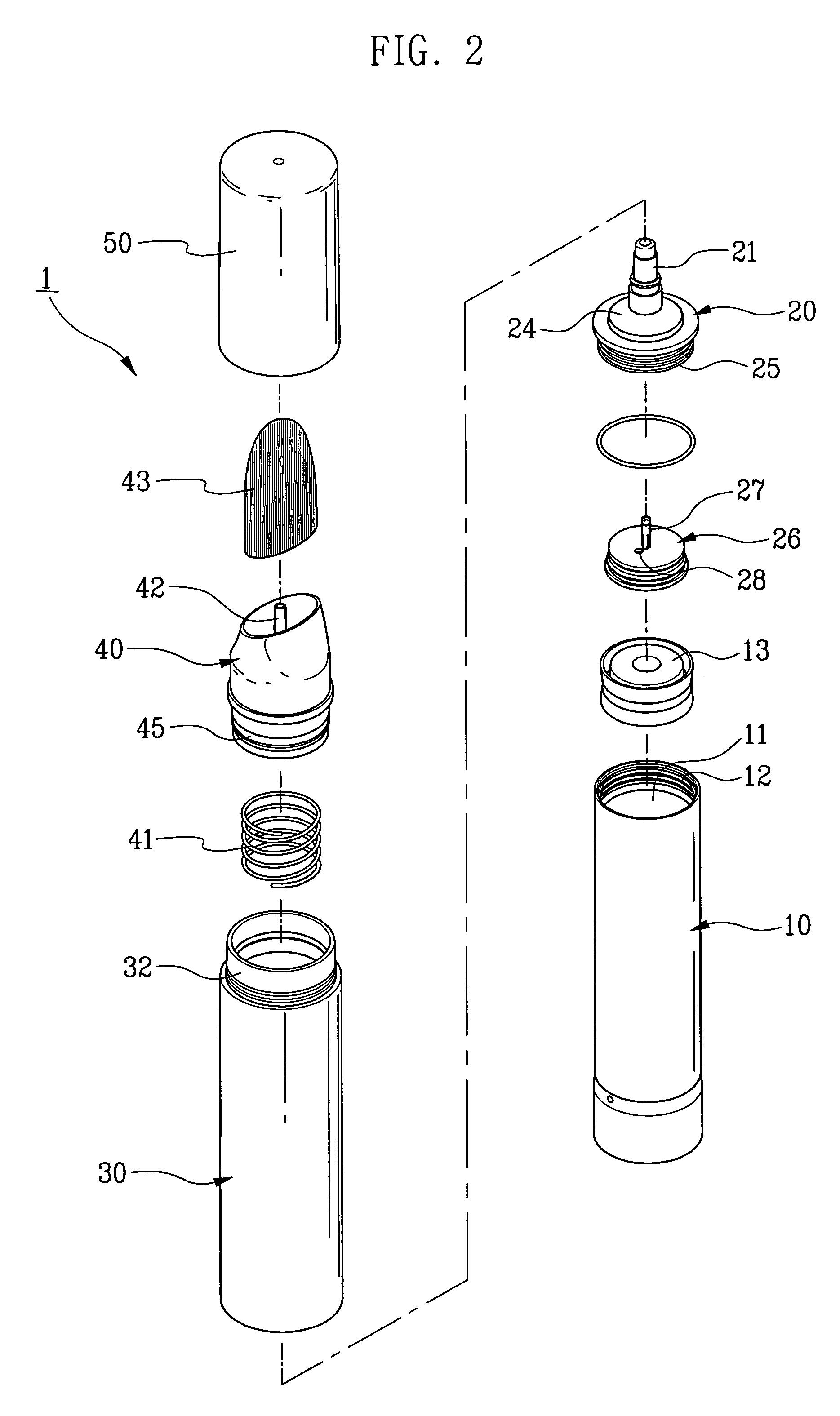
[0022]As illustrated in FIG. 1 and FIG. 3, a receiving part 11 is formed in a inside of inner moving body 10 and is settled a pressing ring 13 and an inner thread 12 is formed in a upper part inner circumference.

[0023]An inner thread 12 that is formed in upper part of the inner moving body 10 is thread coupled with a middle member 20 including a coupling member 25 that is inserted and coupled with a liquid transfer passage 21, a cone type elastic part 24 and a vertical sealing form 26.

[0024]A liquid transfer passage that moves cosmetics is formed in upper part of a middle member 20 that is thread coupled to upper part of the inner moving body, an inner hole 22 is formed in inside bottom part, and an opening valve that is including an opening projection 23a is formed in one side bottom part of the inner hole 22.

[0025]Also, a coupling member 25 including an o...


PUM


Abstract

A cosmetics discharge structure of cosmetics case including a receiving part 11, an inner space part 24a formed to a cone type elastic part 24 through a opening hole 28, a vertical rod 27, an inner hole 22, and an inner space part 24a discharges to a brush 43 through a liquid discharger 42 from the inner hole 22. An inner moving body 10 declines and returns by an expansion of a cone type elastic part 24 formed to the middle member 20 and elastic and repellent force of a spring 41, the vertical rod 27 declines and seals the inner hole 22, closed opening hole 28 opens and a cosmetics including the receiving part 11 will not discharge to the brush 43. The inner hole 22 and the opening hole 28 are open by pressing and releasing inner moving body 10 and the cone type elastic part 24 and the spring 41 that formed in the middle member 20 can be control freely discharge and interception of cosmetics by compressing and the middle member 20 that composed to a liquid transfer passage 21.

Description

CROSS-REFERENCE TO RELATED APPLICATIONS[0001]This application claims the benefits of Korean Patent Application No. 10-2006-0094531, filed on Sep. 28, 2006, in the Korean Intellectual Property Office, the disclosure of which is incorporated herein by reference.BACKGROUND OF THE INVENTION[0002]1. Field of the Invention[0003]The present invention relates to a cosmetics discharge structure of cosmetics case, a cosmetics including in the receiving part moves to a inner space part formed to a cone type elastic part through a opening hole by compressing a receiving part and rising an inner moving body, a vertical rod rises and an inner hole opens by rising an inner moving body to a top, moved cosmetics in an inner space part discharges to a brush through a liquid discharger from the inner hole and releases pushing power to an inner moving body, an inner moving body declines and returns by an expansion of a cone type elastic part formed to the middle member and elastic and repellent force o...

Claims


Application Information

Patent Timeline
Patent Type & Authority Patents(United States)
IPC IPC(8): A46B11/04
CPCA45D34/042A46B11/0027B05B11/3074B05B11/3028B05B11/3032B05B11/3052B05B11/307A46B2200/1046B05B11/0037B05B11/0048B05B11/0038B05B11/028B05B11/1028B05B11/1032B05B11/1052B05B11/107B05B11/1074
Inventor BYUN, YOUNG-KWANG
Owner BYUN YOUNG KWANG
Why Eureka
Try Eureka