RF amplifier with pulse detection and bias control

a pulse detection and bias control technology, applied in amplifiers, amplifiers with semiconductor devices only, amplifiers, etc., can solve problems such as amplifiers becoming more non-linear under pulsed signal conditions, degraded performance, and cdma applications are particularly sensitive to non-linearities and power levels

Inactive Publication Date: 2008-04-08
COMMSCOPE TECH LLC
View PDF29 Cites 3 Cited by
  • Summary
  • Abstract
  • Description
  • Claims
  • Application Information

AI Technical Summary

Benefits of technology

[0026]While the present invention has been illustrated by a description of various embodiments and while these embodiments have been described in considerable detail, it is not the intention of the applicant to restrict or in any way limit the scope of the appended claims to such detail. Additional advantages and modifications will readily appear to those skilled in the art. The invention in its broader aspects is therefore not limited to the specific details, representative apparatus and method, and illustrative examples shown and described. Accordingly, departures may be made from such details without departing from the spirit or scope of applicant's general inventive concept.

Problems solved by technology

CDMA applications are particularly sensitive to non-linearities and power levels.
The transmission of such pulsed data signals through amplifiers that are optimized for non-pulsed voice signals leads to degraded performance.
More specifically, the amplifiers become more non-linear under pulsed signal conditions because of the amplifier's increased gain expansion when operated under such pulsed conditions.
This leads to a non-optimum ACPR performance (6-8 dB higher emissions) under such pulsed signal conditions.

Method used


Image

  • RF amplifier with pulse detection and bias control
  • RF amplifier with pulse detection and bias control
  • RF amplifier with pulse detection and bias control

Examples


Embodiment Construction

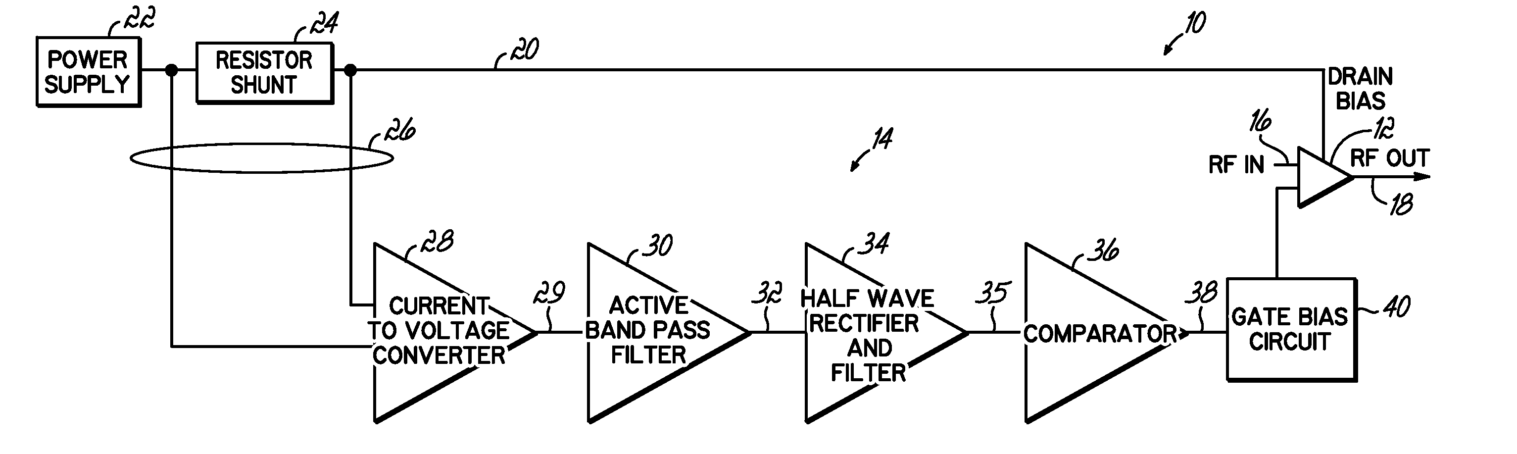
[0012]The present invention provides an amplifier that is able to detect the presence of a pulsed RF signal that is applied to the amplifier, when that signal information is not available from another source, such as the base station. The present application is particularly useful for amplifying both voice and data signals and optimizing the performance of the amplifier for both a non-pulsed input signal (voice signal) and a pulsed input signal (data signal). The invention optimizes the ACPR performance under both pulsed and non-pulsed signal conditions.

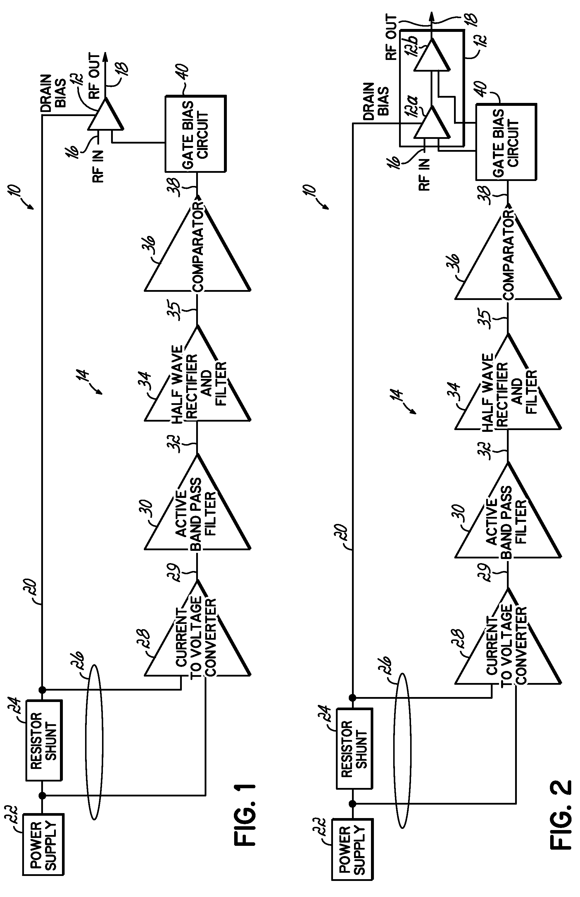
[0013]Referring to FIG. 1, a high level block diagram of one embodiment of the invention is shown in the form of an overall RF amplifier circuit 10 which incorporates an amplifier 12 and a pulse detector circuit 14 coupled with the amplifier for detecting a pulsed RF input signal. As discussed with respect to FIG. 1, amplifier 12 includes at least one amplification stage or may include multiple amplification stages as illustrated in ...


PUM


Abstract

An RF amplifier includes at least one RF amplification stage having an RF input signal and an RF output signal and a power signal circuit with power supply coupled with the amplification stage for providing a power signal to the amplification stage.A bias circuit biases the amplification stage to control its operation.A pulse detection circuit is coupled with the power signal circuit and the bias circuit and detects a voltage from the power signal.The pulse detection circuit analyzes the detected voltage of the power signal and determines if the RF input signal presents a pulsed signal condition or non-pulsed signal condition, and controls the bias circuit for biasing the amplification stage according to the determined condition.

Description

FIELD OF THE INVENTION[0001]The present invention relates generally to RF amplifiers, and particularly to RF amplifiers utilized for the transmission of voice and data signals.BACKGROUND OF THE INVENTION[0002]In wireless communication applications, various signal formats are utilized to transfer both voice signals as well as data signals. In a typical wireless communication system, such as a cellular system, a plurality of base stations utilizing transceivers with RF amplifiers are used to transceive signals with a plurality of mobile devices, such as cellular phones. Traditionally, such wireless communications were focused upon the transmission of voice signals as telephonic applications drove the earliest needs for such systems. However, data applications have become more prevalent such that it is desirable that a base station be able to adequately handle both voice signals and data signals in their various forms.[0003]In more modern wireless communication protocols, such as CDMA ...

Claims


Application Information

Patent Timeline
Patent Type & Authority Patents(United States)
IPC IPC(8): H03G3/10
CPCH03F1/0261H03F1/30H03F3/19H03F2200/18H03F2200/78
Inventor HAMPARIAN, SIMON
Owner COMMSCOPE TECH LLC
Why Eureka
Try Eureka