Analog input device

a technology of input device and input input, which is applied in the direction of fluid pressure computing, instruments, contact mechanisms, etc., can solve the problems of poor linearity of input-output characteristics, improve input-output response, and improve the force transmission efficiency of rubber members

Inactive Publication Date: 2008-08-19
ALPS ALPINE CO LTD
View PDF8 Cites 0 Cited by
  • Summary
  • Abstract
  • Description
  • Claims
  • Application Information

AI Technical Summary

Benefits of technology

[0016]In order to overcome the above problems of the conventional art, an object of the present invention is to provide an analog input device that enhances the force transmission efficiency of a rubber member, that improves the input-output response, and that achieves good linearity of the input-output characteristic.
[0018]When the key top is pressed, a pressing portion of the rubber member is first pressed down, a movable electrode touches a resistor, and the entire rubber member is then distorted. Therefore, an analog output can be quickly produced in response to the pressing of the key top, and a dead zone that easily appears in the input-output characteristic can be removed or reduced.
[0023]According to the above-described analog input device, since the contact area between the movable electrode and the resistor can be gradually increased, linearity of the input-output characteristic can be enhanced.

Problems solved by technology

Consequently, the linearity of the input-output characteristic is poor.

Method used


Image

  • Analog input device
  • Analog input device
  • Analog input device

Examples


first embodiment

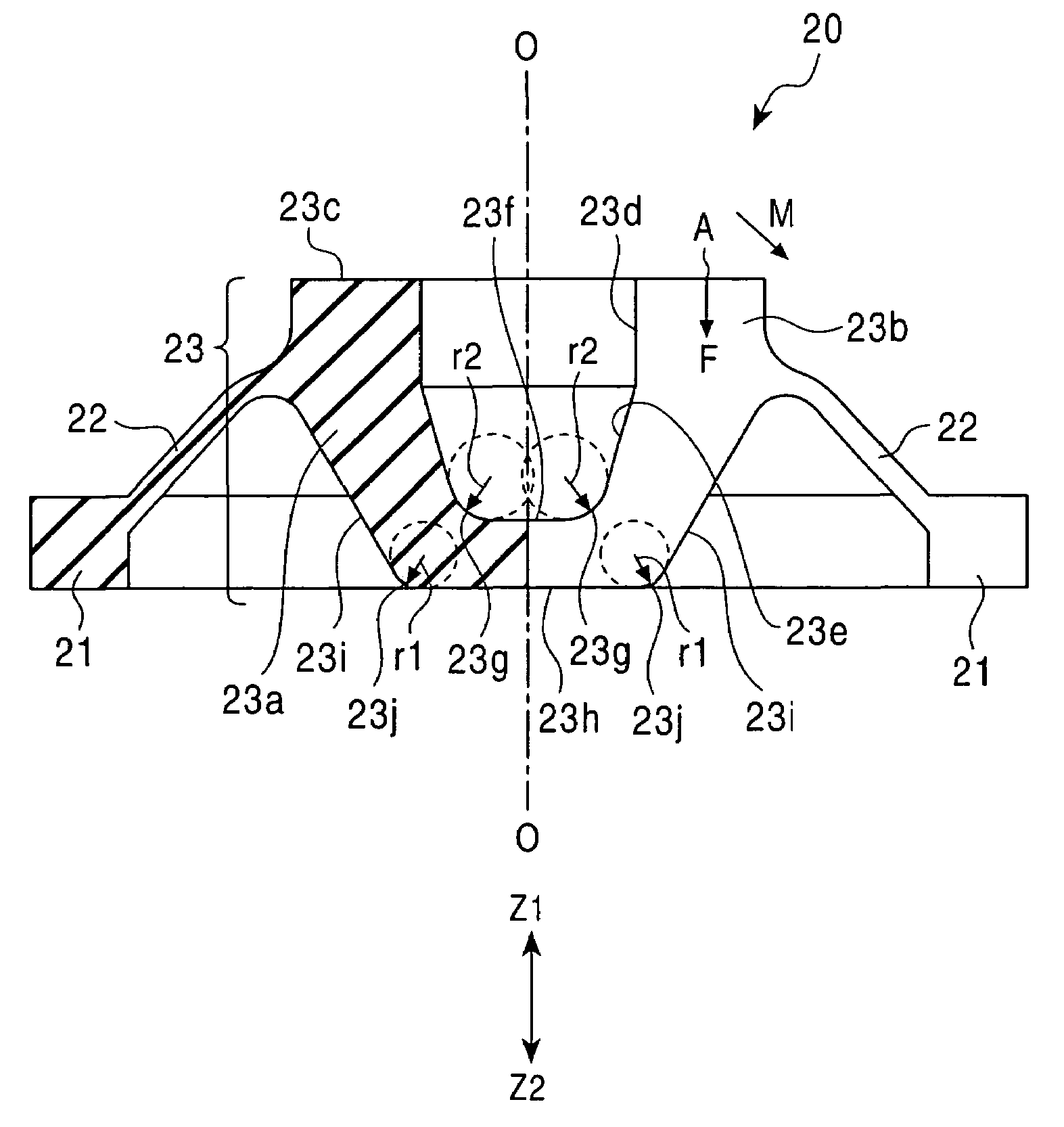
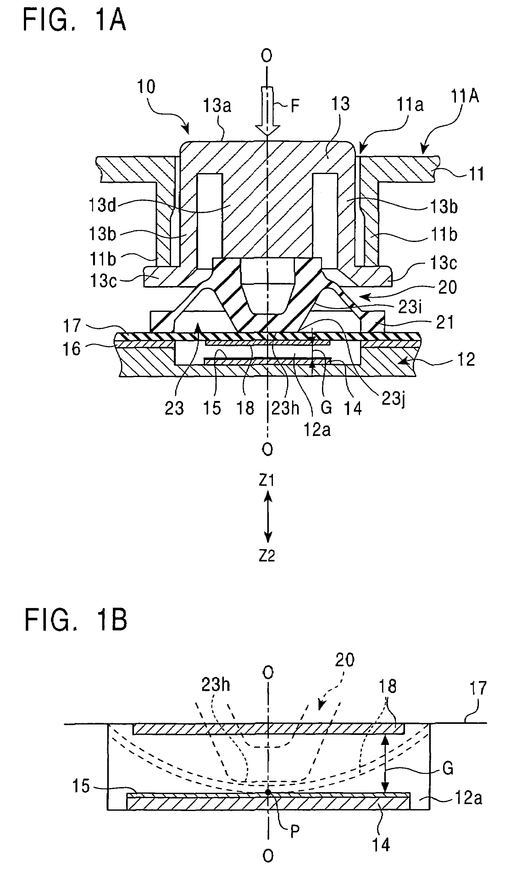
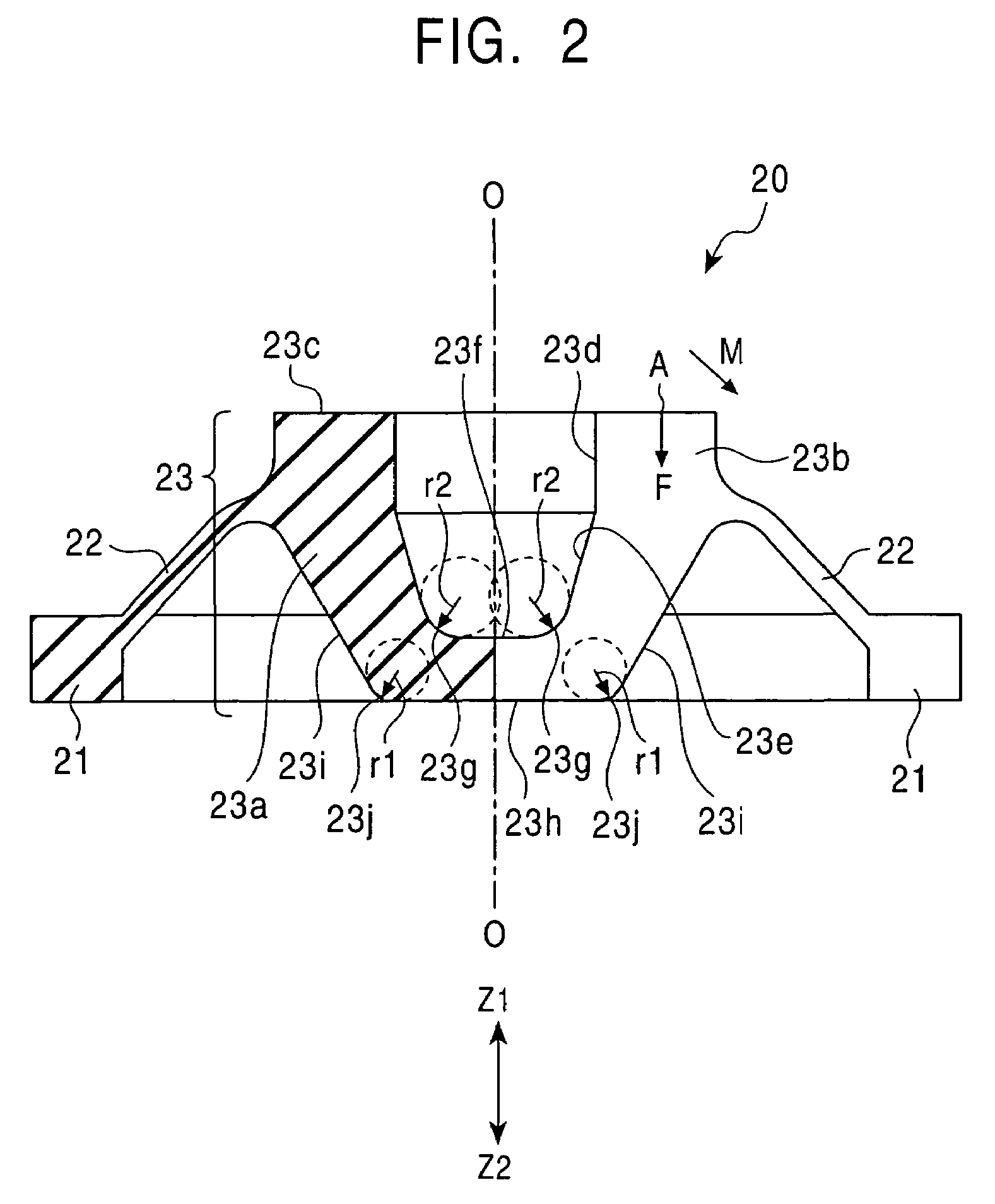
[0035]FIG. 1A is a cross-sectional view of an analog input device according to the present invention, FIG. 1B is an enlarged cross-sectional view of a section of the analog input device including a deformed movable electrode and a resistor, and FIG. 2 is a cross-sectional view of a rubber member.

[0036]An analog input device 10 shown in FIG. 1A is, for example, one of the four keys that constitute a cross key of a controller for a game machine.

[0037]As shown in FIG. 1A, the analog input device 10 is provided between an upper case 11 and a lower case 12. The upper case 11 has an opening 11a, and a key top 13 is supported inside the opening 11a so as to be pressed in the Z1-Z2 directions. A face portion 13a serving as an upper surface of the key top 13 slightly protrudes from a surface 11A of the upper case 11 in the Z1-direction. A side portion 13b extends from the face portion 13a in the Z2-direction, and a flange portion 13c is provided around the lower end of the side portion 13b. ...

second embodiment

[0050]FIG. 3 is a cross-sectional view of a rubber member according to the present invention.

[0051]In the second embodiment, a rubber member 30 shown in FIG. 3 has a structure similar to that of the rubber member 20 shown in FIG. 2, but is different in the following respects.

[0052]That is, as shown in FIG. 3, a bottom face of an inner wall 33e that defines a cavity in a pressing portion 33 is formed only by a second round surface 33g having a predetermined radius (second radius) r3.

[0053]A bottom portion 33h of an outer surface of the pressing portion 33 is formed, for example, by a flat surface or a curved surface made of a part of a spherical surface having a predetermined radius of curvature.

[0054]First round surfaces 33j having a predetermined radius (first radius) r1 are disposed symmetrically with respect to the axis O-O between the bottom portion 33h and an outer side face 33i. The bottom portion 33h is disposed close to or in contact with the surface of the above-described s...


PUM


Abstract

In an analog input device, a rubber member is provided between a key top and a movable electrode of an analog-quantity generating unit. A dead zone can be removed or reduced by forming a bottom portion of the rubber member of a flat or curved face. Furthermore, since first round surfaces are connected to an outer side face, the linearity of the input (e.g., a load)-output (voltage) characteristic can be enhanced.

Description

[0001]This application claims the benefit of priority to Japanese Patent Application No. 2003-199266, herein incorporated by reference.BACKGROUND OF THE INVENTION[0002]1. Field of the Invention[0003]The present invention relates to an analog input device mounted in, for example, a controller for a game machine, and more particularly, to an analog input device that improves the output characteristic with respect to changes in load or stroke during a key-pressing operation.[0004]2. Description of the Related Art[0005]FIG. 7 is a cross-sectional view showing a state of a known analog input device before deformation, and FIGS. 8A and 8B are graphs showing the input-output characteristic of the analog input device. In FIG. 8A, the input represents the load, and the output represents the number of bits obtained by subjecting the analog output voltage between a movable electrode and a resistor to A / D conversion. In FIG. 8B, the input represents the stroke, and the output represents the num...

Claims


Application Information

Patent Timeline
Patent Type & Authority Patents(United States)
IPC IPC(8): G06F3/02G06G5/00H01H1/10H01H3/12H01C10/10G06F3/033H01H13/00H01H13/20H01H13/52
CPCA63F13/06G06F3/0362A63F2300/1056A63F2300/1043A63F13/218A63F13/24
Inventor NIITSUMA, HIROFUMIWATANABE, KAZUTOSHIINAMUARA, JUNICHISATO, ISAO
Owner ALPS ALPINE CO LTD
Why Eureka
Try Eureka