
Self-adaptive assembled multistage adjustable blade operating mechanism

A control mechanism and assembled technology, applied in the field of aero-engines, can solve problems such as force transmission loss and interference, and achieve the effect of improving force transmission efficiency and avoiding interference.

Active Publication Date: 2019-08-16
AECC COMML AIRCRAFT ENGINE CO LTD
View PDF7 Cites 0 Cited by
  • Summary
  • Abstract
  • Description
  • Claims
  • Application Information

AI Technical Summary

Problems solved by technology

[0008] The technical problem to be solved by the present invention is to overcome the defect that the adjustable vane operating mechanism in the prior art is easy to cause force transmission loss, and it is easy to cause the connecting rod assembly to interfere with the connected or adjacent parts, and to provide an adaptive assembly multi-stage adjustable vane operating mechanism

Method used


Image

  • Self-adaptive assembled multistage adjustable blade operating mechanism
  • Self-adaptive assembled multistage adjustable blade operating mechanism
  • Self-adaptive assembled multistage adjustable blade operating mechanism

Examples


Embodiment Construction

[0029] In order to make the above objects, features and advantages of the present invention more comprehensible, specific implementations of the present invention will be described in detail below in conjunction with the accompanying drawings.

[0030] Embodiments of the present invention will now be described in detail with reference to the accompanying drawings. Reference will now be made in detail to the preferred embodiments of the invention, examples of which are illustrated in the accompanying drawings. Wherever possible, the same numbers will be used throughout the drawings to refer to the same or like parts.

[0031] In addition, although the terms used in the present invention are selected from well-known and commonly used terms, some terms mentioned in the description of the present invention may be selected by the applicant according to his or her judgment, and the detailed meanings thereof are set forth herein described in the relevant section of the description. ...


PUM


Abstract

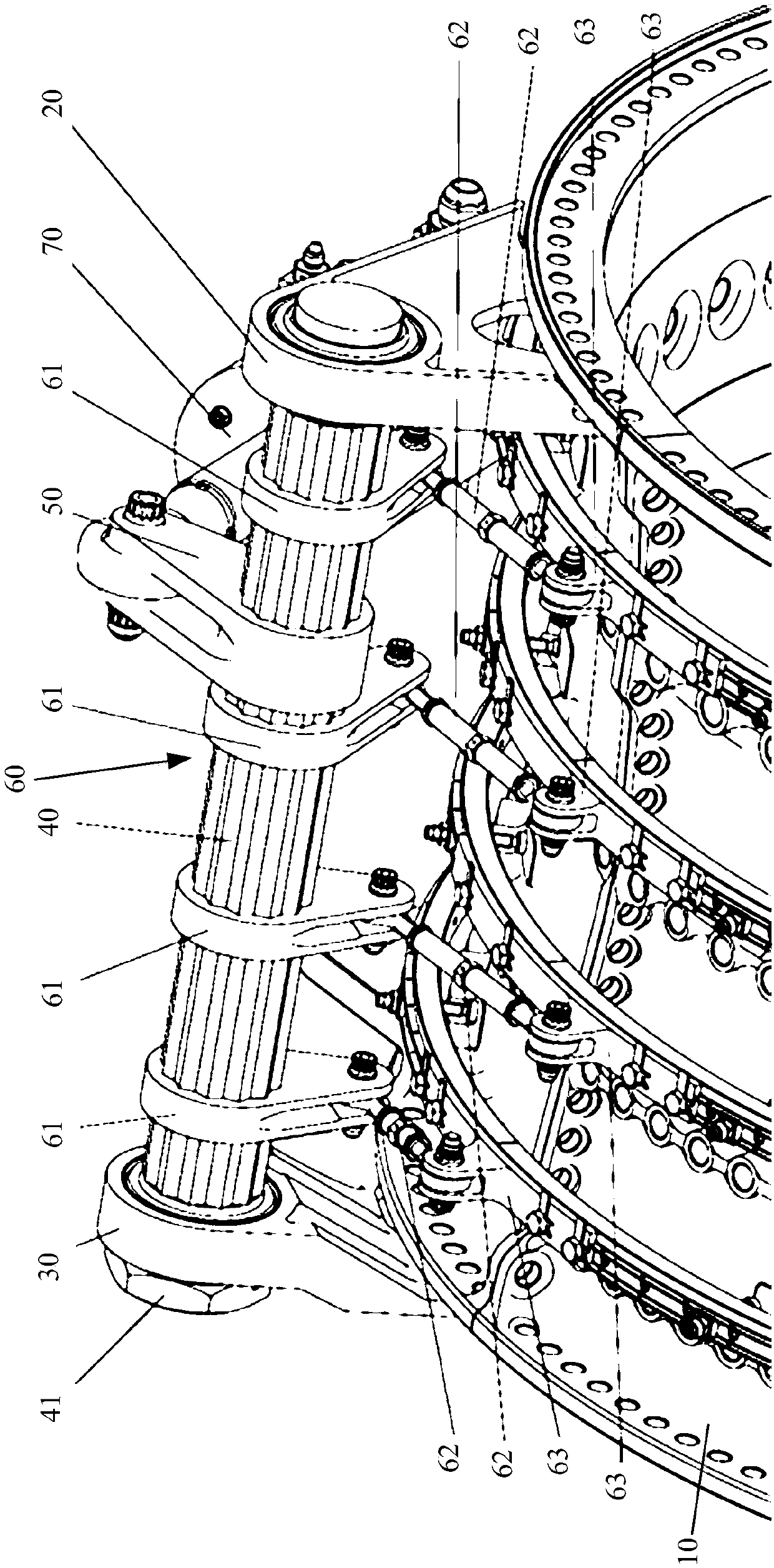
The invention provides a self-adaptive assembled multistage adjustable blade operating mechanism which is mounted on a cartridge receiver. The self-adaptive assembled multistage adjustable blade operating mechanism comprises a front mounting seat, a back mounting seat, a torsion bar cross beam, a driving end and a multistage driven mechanism. The front mounting seat and the back mounting seat areseparately mounted at two ends of the cartridge receiver, and the torsion bar cross beam is mounted between the front mounting seat and the back mounting seat; one end of the driving end is connectedto a hydraulic actuating barrel while the other end of the driving end is mounted on the torsion bar cross beam and the driving end is driven by the hydraulic actuating barrel to drive the torsion barcross beam to rotate, and the driving end can slide relatively along the axial direction of the torsion bar cross beam. One end of the driven mechanism is mounted on the cartridge receiver while theother end of the driving mechanism is mounted on the torsion bar cross beam and the driven mechanism is driven by the torsion bar cross beam. As the included angles between the driving end of the torsion bar and the driven ends of stages are adjustable, changes of adjusting angles and ranges of adjustable blades of stages are adapted greatly. The positions of the driven ends of stages are adjustedself-adaptively, so that the force transmission efficiency of the operating mechanism is improved and intervention among parts is avoided.

Description

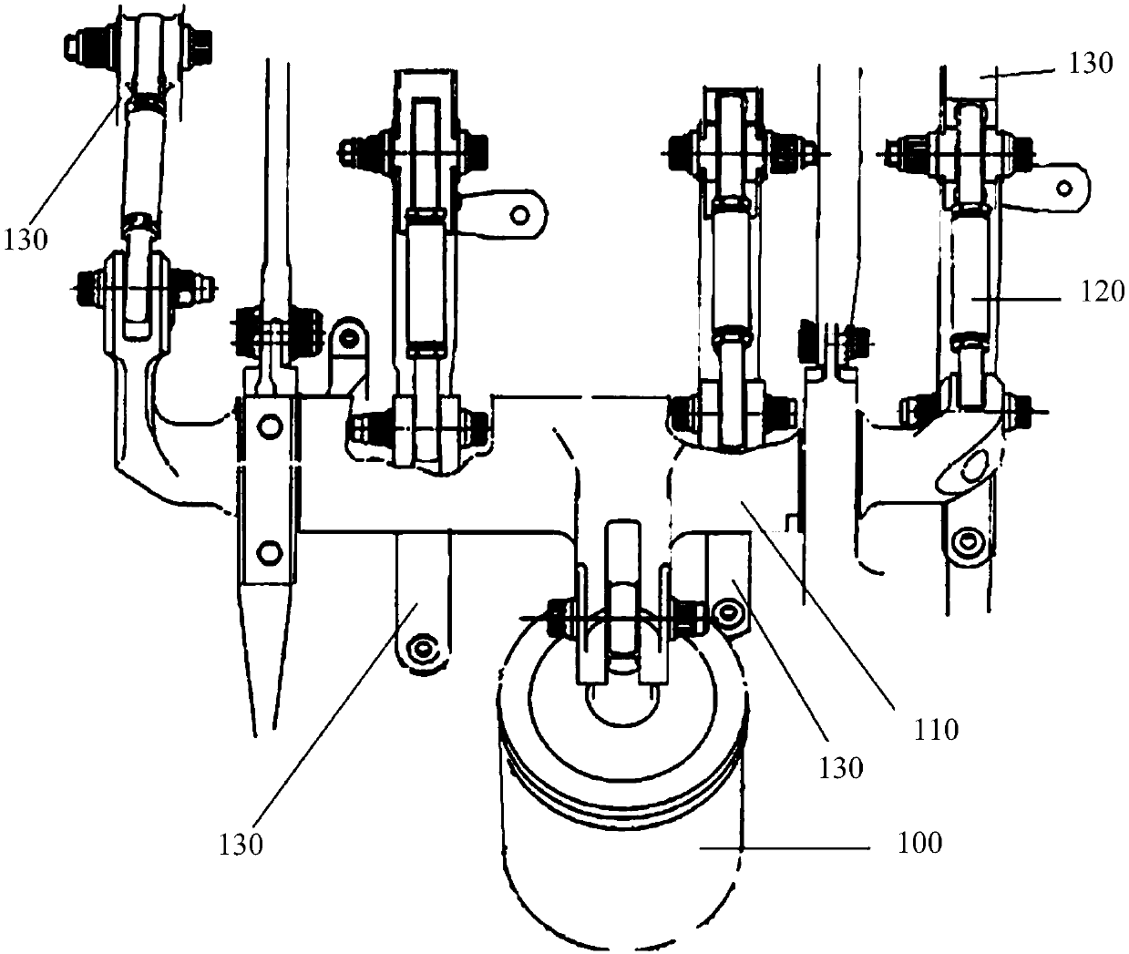
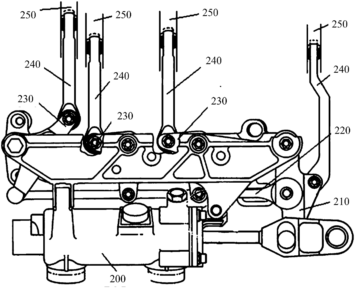
technical field [0001] The invention relates to the field of aero-engines, in particular to an adaptive assembled multi-stage adjustable blade control mechanism. Background technique [0002] In the field of aero-engines, adjustable blades can be used to improve the stable working range of compressors, and are widely used in aero-engines. Generally, there are multiple stages of adjustable blades in the compressor, and the angles adjusted by each stage are different. In order to make the stages work in harmony, a set of control mechanism needs to be designed. [0003] The existing designs mainly include two types, one is the torsion bar type adjustable blade control mechanism, such as the GE90 series. figure 1 It is a schematic diagram of a torsion bar type adjustable vane operating mechanism in the prior art. Such as figure 1 As shown, the hydraulic cylinder 100 drives the torsion bar 110 to rotate, and the driving end and the driven end on the torsion bar 110 rotate at t...

Claims


Application Information

Patent Timeline
Patent Type & Authority Applications(China)
IPC IPC(8): F04D27/00F04D29/56F02C9/20
CPCF02C9/20F04D27/002F04D29/563
Inventor 郭绍唱林清松聂聪刘先智叶文勋
Owner AECC COMML AIRCRAFT ENGINE CO LTD
Learn More