Color display device using separate diffracted light and illumination light

a color display device and diffracted light technology, applied in the field of color display devices, can solve the problems of reducing operational reliability, affecting the operation of the above-described laser scanning type light beam scanning apparatus, and unable to achieve significant improvement in scanning speed, etc., and achieve the effect of simple optical system

Inactive Publication Date: 2008-04-08
SAMSUNG ELECTRO MECHANICS CO LTD
View PDF4 Cites 2 Cited by
  • Summary
  • Abstract
  • Description
  • Claims
  • Application Information

AI Technical Summary

Benefits of technology

[0024]Accordingly, the present invention has been made keeping in mind the above problems occurring in the prior art, and an object of the present invention is to provide a color display device in which a simple optical system can be realized by separating diffracted light from illumination light.

Problems solved by technology

It is difficult for the above-described laser scanning type light beam scanning apparatus to achieve high-speed printing, due to the low switching speed of the laser diode 10 and the speed problem of the polygon mirror 13.
However, the high-speed motor is expensive, and the motor operating at high speed generates heat, vibration and noise, thus degrading operational reliability, so that a significant improvement in scanning speed cannot be expected.
Meanwhile, the rotational speed of the optical reflector and the image clock cannot comply with the large number of optical scans.
However, the surface emitting laser has a problem in that an output light beam has an unstable polarization direction.
Further, the difference in intensity results in irregular pitch in an image, thus considerably degrading image quality.

Method used


Image

  • Color display device using separate diffracted light and illumination light
  • Color display device using separate diffracted light and illumination light
  • Color display device using separate diffracted light and illumination light

Examples


Embodiment Construction

[0037]The construction of a color display device using separate diffracted light and illumination light according to the present invention is described in detail with reference to the accompanying drawings below.

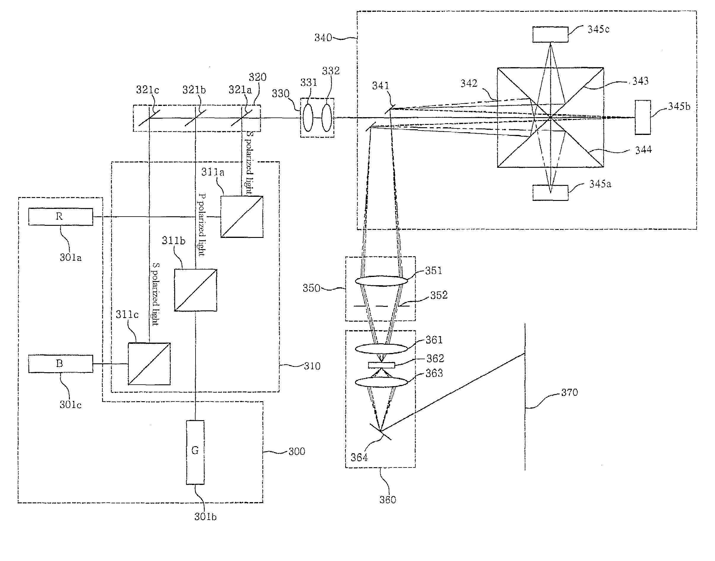
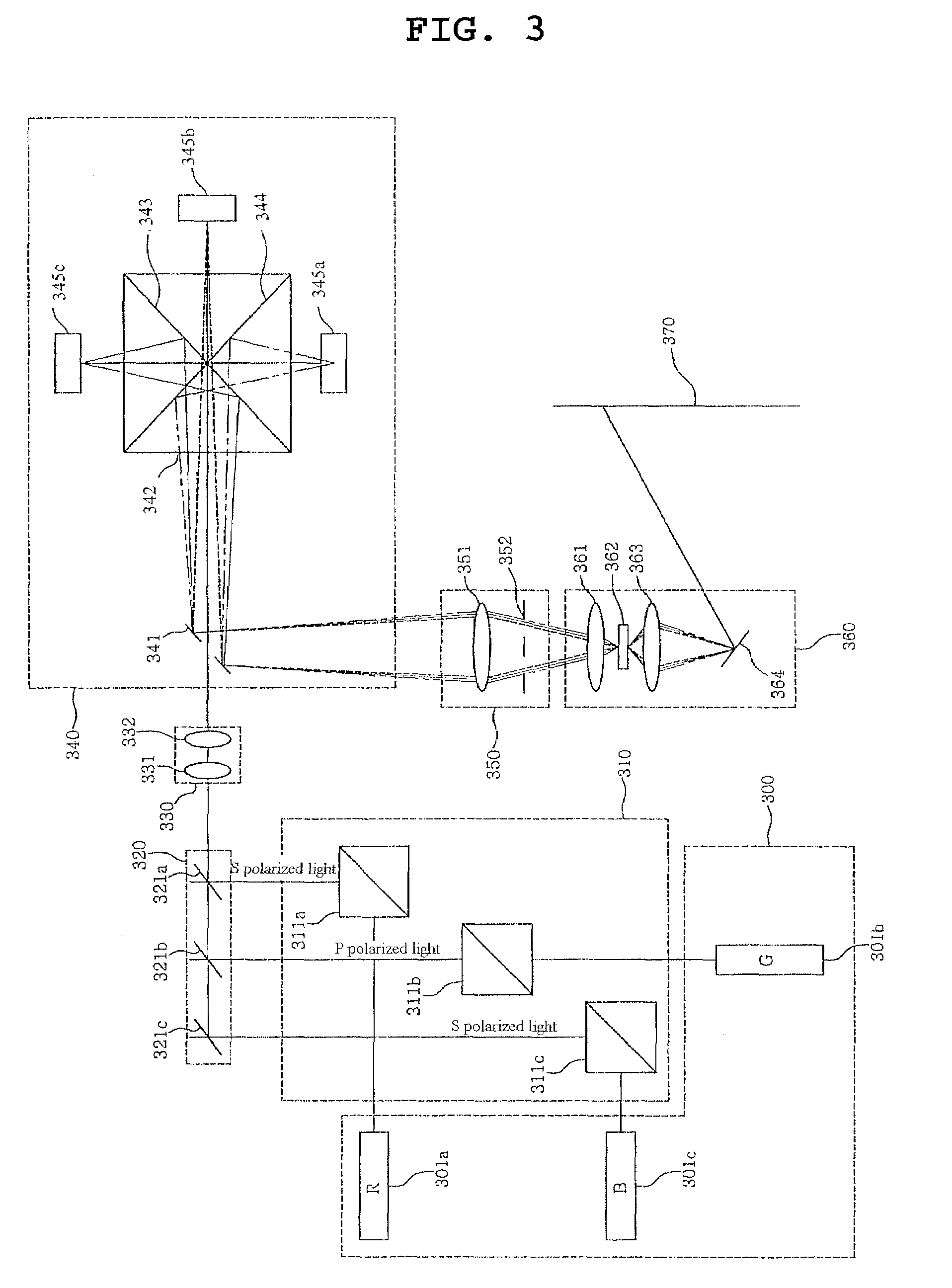
[0038]FIG. 3 shows the configuration of a color display device using separate diffracted light and illumination light according to an embodiment of the present invention.

[0039]Referring to FIG. 3, the color display device using separate diffracted light and illumination light according to the embodiment of the present invention includes a light source system 300 composed of a plurality of light sources 301a to 301c, a polarized light separation unit 310 composed of a plurality of Polarized Beam Splitters (PBSs) 311a to 311c, a condenser unit 320 composed of one mirror 321c and a plurality of dichroic mirrors 321a and 321b, an illumination lens system 330 composed of a cylinder lens 331 and a collimator lens 332, a light modulation system 340 composed of a mirror 341 for sepa...


PUM

PropertyMeasurementUnit
thicknessaaaaaaaaaa
reflection angleaaaaaaaaaa
widthaaaaaaaaaa

Abstract

A display device is disclosed. The display device includes a condenser unit, an illumination lens system, a plurality of diffractive light modulators, a mirror for separating illumination light from diffracted light, a polarized beam separator, a filter unit and a projection unit.

Description

BACKGROUND OF THE INVENTION[0001]1. Field of the Invention[0002]The present invention relates generally to a color display device and, more particularly, to a color display device in which a simple optical system can be realized by separating diffracted light from illumination light.[0003]2. Description of the Related Art[0004]A light beam scanning apparatus is an apparatus for producing an image by causing a light beam to form spots on a photosensitive medium through scanning in an image forming apparatus such as a laser printer, a display device, a Light Emitting Diode (LED) printer, an electrophoto copying machine or a word processor.[0005]As image forming apparatuses develop toward compactness, high speed and high resolution, light beam scanning apparatuses have been accordingly researched and developed to have the characteristics of compactness, high speed and high resolution.[0006]Light beam scanning apparatuses for image forming apparatuses may be mainly classified into laser...

Claims


Application Information

Patent Timeline
Patent Type & Authority Patents(United States)
IPC IPC(8): G02B27/12G02F1/00G03B21/28H04N5/74
CPCG02B26/0808G02B27/283G02B27/46H04N9/3132B41J2/471G02B26/108G02B26/123
Inventor YANG, HAENG SEOKYUN, SANG KYEONGOH, KWAN YOUNG
Owner SAMSUNG ELECTRO MECHANICS CO LTD
Why Eureka
Try Eureka