Wavefront characterization of corneas

a wavefront and corneal technology, applied in the field of wavefront sensing, can solve the problems of inability to conclusively tell, either visually or under a microscope, and the cornea is generally unsuitable for corneal transplantation, and achieves scintillation and static aberration, aberrations that produce scintillation

Inactive Publication Date: 2005-04-28
OTTEN LEONARD JOHN III +3
View PDF3 Cites 3 Cited by
  • Summary
  • Abstract
  • Description
  • Claims
  • Application Information

AI Technical Summary

Benefits of technology

[0014] It is yet another object of the present invention to provide a holder for a donor cornea t...

Problems solved by technology

As beneficial as these procedures are, the individual corneas are permanently altered, which makes them unsuitable for corneal transplanting.
Unfortunately, it is generally not possible to conclusively tell, either visually or under a microscope, whether such a donor cornea has been subjected to a surgica...

Method used


Image

  • Wavefront characterization of corneas
  • Wavefront characterization of corneas
  • Wavefront characterization of corneas

Examples


Embodiment Construction

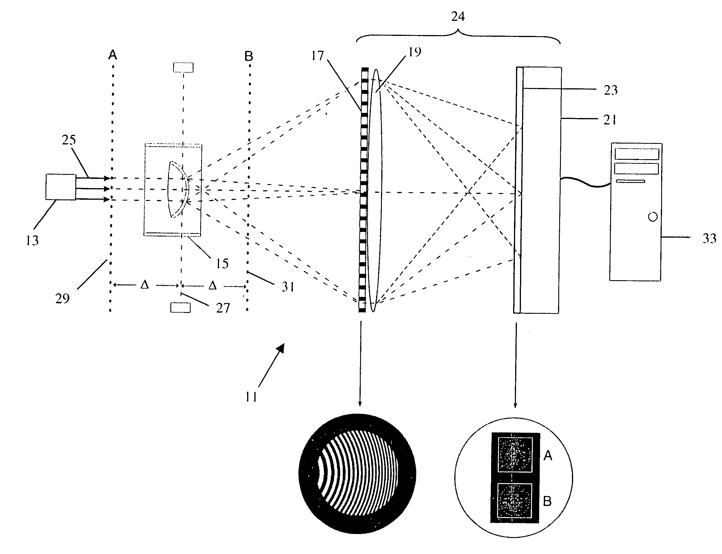
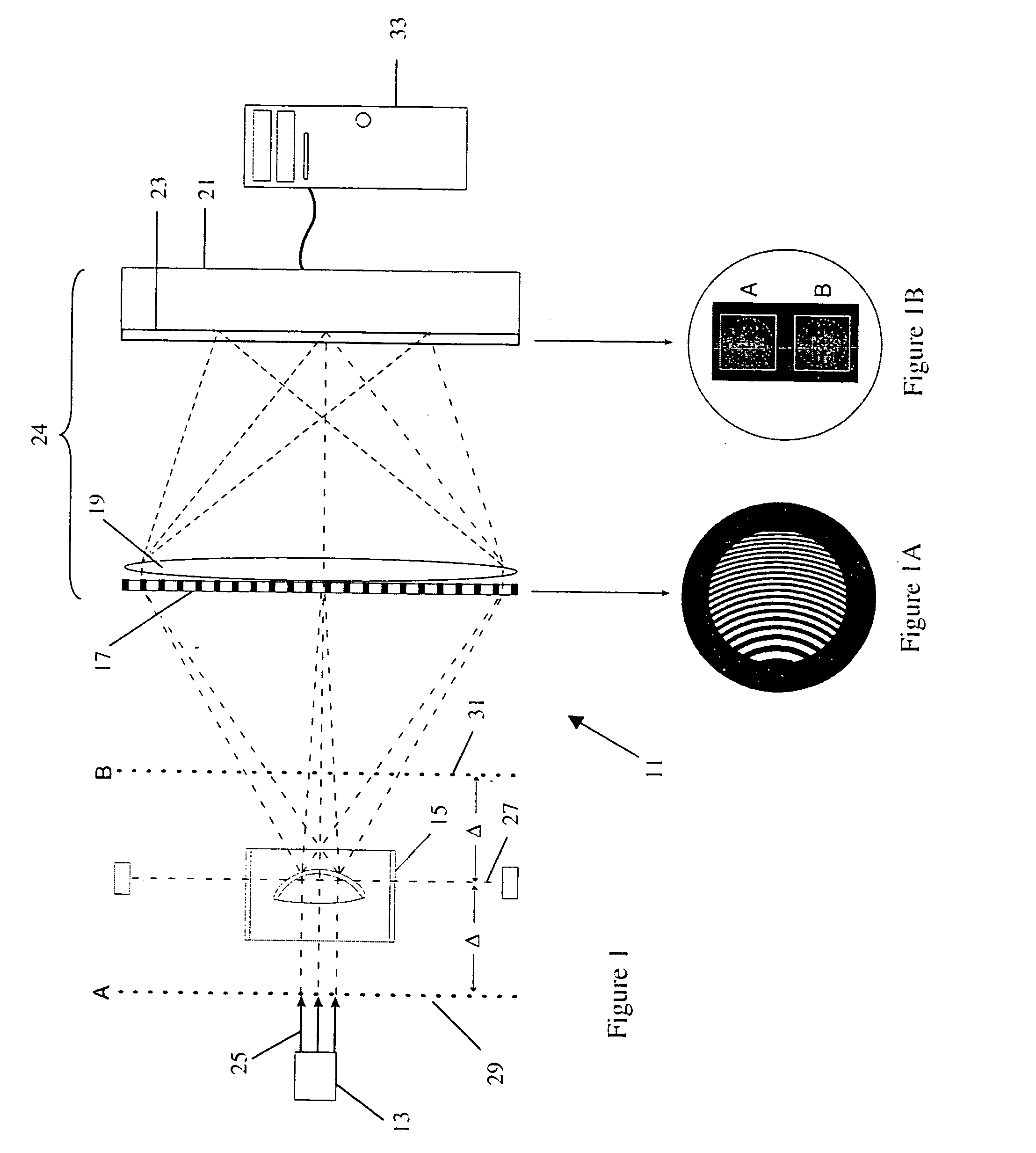
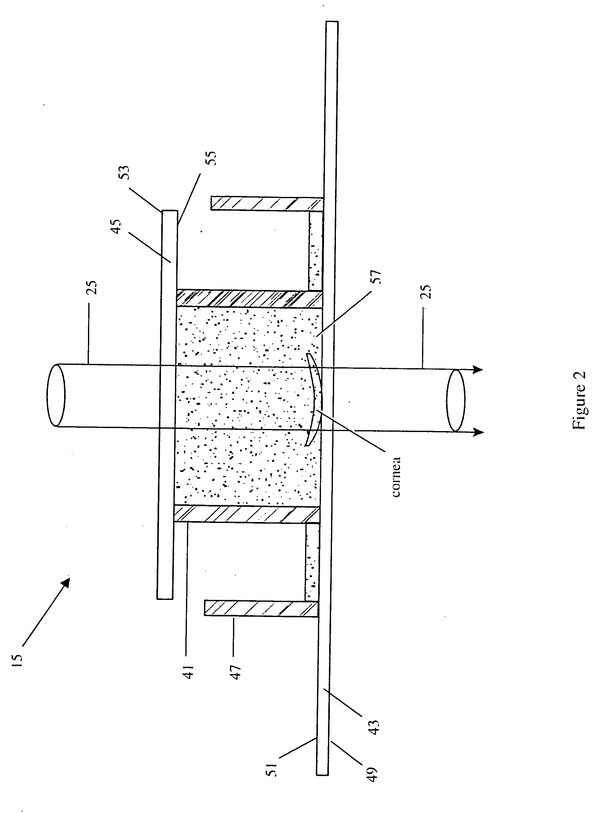
[0040] With reference to FIG. 1, the apparatus 11 for determining whether an in vitro cornea has been modified (either surgically or otherwise) includes a source of collimated coherent light 13, a cornea container 15, a distorted diffraction grating 17, a high quality imaging lens (or lens set) 19, and a detector 21 (either film or electronic) having a detector plane 23. (Grating 17, lens 19 and detector 21 are sometimes referred to as wavefront sensor 24.) Apparatus 11 also includes a beam path 25, a pupil plane 27, first virtual plane 29, second virtual plane 31, and a computer 33. Computer 33 is connected to detector 21, via a data acquisition device such as a frame grabber (located within the computer housing). Computer 33 stores the images form detector 21, determines the wavefront from the stored images, and the analyzes the wavefront for the characteristics that identify an altered cornea (e.g. compares the wavefronts to a stored norm). The representation of the virtual plane...


PUM


Abstract

Apparatus for determining if a cornea (whether in vitro or in vivo) has been modified (either surgically or otherwise). The method includes the steps of: passing a beam of collimated light a (either coherent or incoherent) through the cornea to produce a distorted wavefront; determining the characteristics of the distorted wavefront; and analyzing the distorted wavefront for characteristics that identify the presence of a modification. The analysis of the distorted wavefront can be for the presence of higher order aberrations, or Gausian characteristics which are indicative of modifications. More particularly, the method includes the steps of providing an optical system that has a pupil plane and an image plane at a detector; positioning the cornea in the pupil plane; passing a collimated beam of light through the cornea to produce at least two images in the image plane; determining the characteristics of the distorted wavefront; and analyzing the distorted wavefront for characteristics that identify the presence of a modification. The apparatus includes: a source of collimated light: an optical system including a distorted grating and an imaging lens (which have a pupil plane, first and second virtual planes, and an image plane); structure for positioning the cornea in the pupil plane; and a computer. The structure for positioning the cornea (which is immersed in a suitable storage fluid) includes first and second plano/plano lenses. The first and second plano lens, which are substantially and perpendicular to and centered with respect to the axis, have less than λ/10 total distortions.

Description

FIELD OF THE INVENTION [0001] This invention relates to the use of wavefront sensing to determine whether or not a cornea has been altered (due to corrective surgery, or accident). More specifically, the present invention relates to the use of wavefront sensing using a distorted defraction grating to identify corneas (whether in vitro or in vivo) that have been surgically modified (e.g., radical keratotomy (RK), excimer laser photorefractive keratectomy (PRK), laser-assisted in situ keratomileusis (LASIK) and automated lamellar keratoplasty (ALK)). BACKGROUND OF THE INVENTION [0002] In the United States about 40,000 corneal transplant operations are performed each year. While success of such surgery may depend upon a number of other factors, one factor that always has an effect on the outcome is the condition of the donor cornea. In the United States, a donor cornea must be transplanted within 7 days of harvesting. Outside the United States donor corneas may be used up to 14 days af...

Claims


Application Information

Patent Timeline
IPC IPC(8): A61B3/103A61B3/107G01J9/00
CPCA61B3/1015G01J9/00A61F2/14A61B3/107A61F2/142
Inventor OTTEN, LEONARD JOHN IIIERRY, GAVIN R. G.WOODS, SIMON S.HARRISON, PAUL
Owner OTTEN LEONARD JOHN III
Why Eureka
Try Eureka