Projection stereoscopic display

a stereoscopic display and projection technology, applied in the field of projection stereoscopic displays, can solve the problems achieve the effects of increasing the number of components and light loss, reducing power consumption, and high light condensing property

Inactive Publication Date: 2013-05-28
SONY CORP
View PDF21 Cites 3 Cited by
  • Summary
  • Abstract
  • Description
  • Claims
  • Application Information

AI Technical Summary

Benefits of technology

[0008]However, in the case where a polarized light source such as a laser is used, it is necessary to convert light into a non-polarization state in advance, thereby the number of components and light loss increase. A laser light source has lower power consumption than a lamp or a light-emitting diode, and has a high light condensing property and extremely high color purity, so a projector with higher efficiency and a wide color gamut is achievable. Moreover, by the above-described projector using the reflective liquid crystal panels, high-definition and large-screen stereoscopic display is achievable at low cost. Therefore, an optical configuration in which a laser having linear polarization as a light source is usable as-is necessary.
[0009]It is desirable to provide a projection stereoscopic display using a linearly polarized light source and achieving stereoscopic display by a single projector using a reflective liquid crystal panel with a simple optical system.
[0012]In the projection stereoscopic display according to the embodiment of the invention, as functions of the first polarizing device and the second polarizing device, only a function of polarization-splitting reflected light from the reflective liquid crystal panel and combining two kinds of pictures is necessary, and a function of distributing incident light to the reflective liquid crystal panel is not necessary. Therefore, a laser having a high light condensing property and low power consumption is usable as a linearly polarized light source with a simple optical system, and a projection stereoscopic display with higher efficiency and higher performance than that in related art is achievable by using the laser.

Problems solved by technology

However, in the case where a polarized light source such as a laser is used, it is necessary to convert light into a non-polarization state in advance, thereby the number of components and light loss increase.

Method used


Image

  • Projection stereoscopic display
  • Projection stereoscopic display
  • Projection stereoscopic display

Examples


application example 1

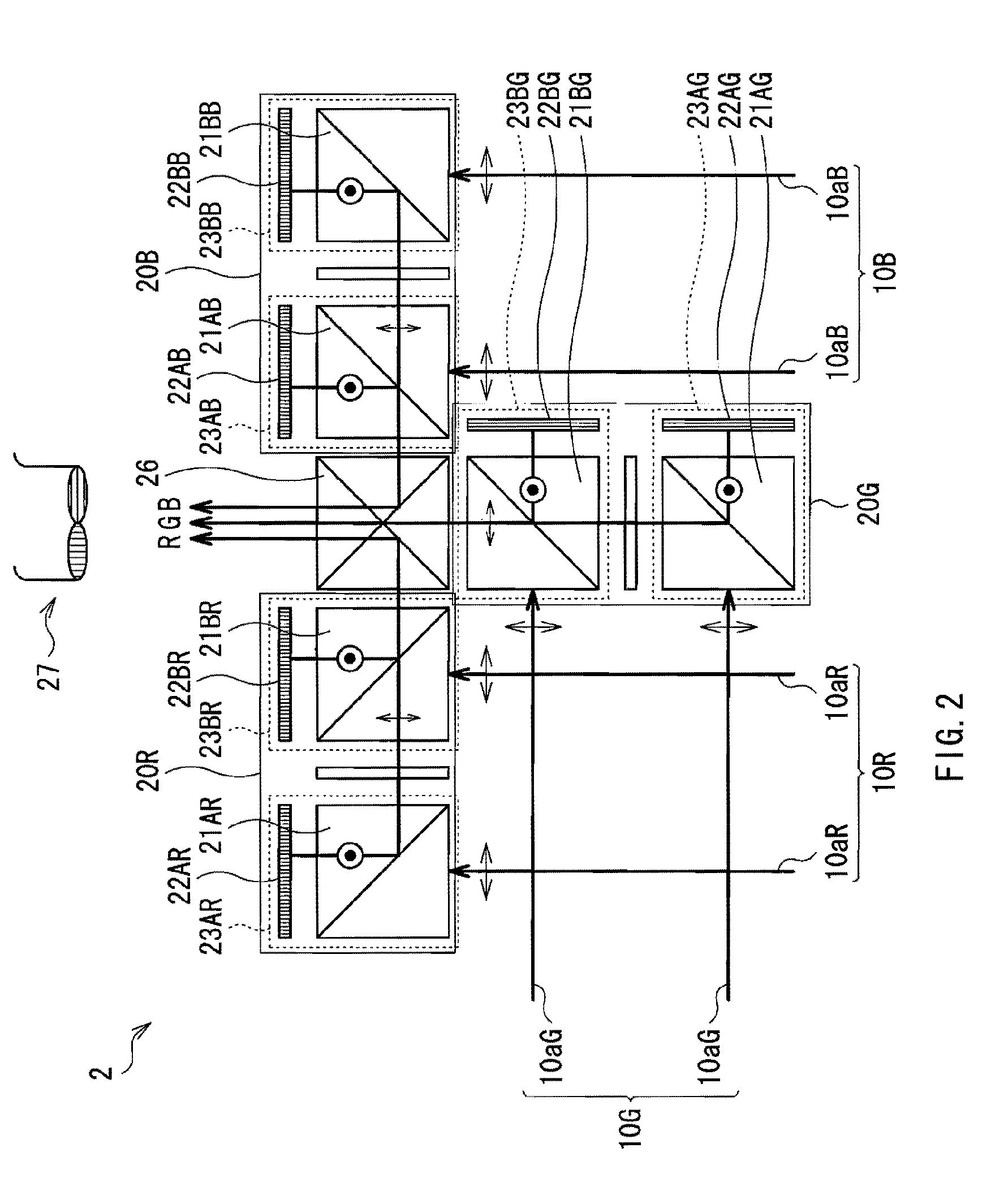
[0043]A stereoscopic display 2 illustrated in FIG. 2 has a configuration in which stereoscopic display optical systems 20 in the above-described stereoscopic display 1 are combined to allow color display of three primary colors R (red), G (green) and B (blue). In this case, reference numerals for components are denoted corresponding to the colors RGB such as, for example, stereoscopic display optical systems 20R, 20G and 20B. The stereoscopic display 2 includes the stereoscopic display optical systems 20R, 20G and 20B and a multiplexing prism 26 for combining pictures of these colors emitted from the stereoscopic display optical systems 20R, 20G and 20B.

[0044]In other words, in the stereoscopic display 2, as in the case of the above-described embodiment, the stereoscopic display optical system 20R into which red laser light 10aR has entered emits a red picture formed by superimposing right and left pictures. Likewise, the stereoscopic display optical system 20G into which green lase...


PUM

PropertyMeasurementUnit
colorsaaaaaaaaaa
color purityaaaaaaaaaa
coloraaaaaaaaaa

Abstract

A projection stereoscopic display includes: a stereoscopic display optical system receiving linearly polarized light from the light source and displaying a first picture and a second picture both having binocular parallax by linearly polarized light with polarization directions orthogonal to each other, in which the stereoscopic display optical system includes: a reflective liquid crystal panel modulating and reflecting linearly polarized light from the light source in response to a picture signal, a first polarizing device splitting the first picture from reflected light from the reflective liquid crystal panel, a retardation device converting the polarization direction of the first picture into a direction orthogonal thereto, and a second polarizing device splitting the second picture from reflected light from the reflective liquid crystal panel, and superimposing the second picture on the first picture of which the polarization direction is converted by the retardation device.

Description

BACKGROUND OF THE INVENTION[0001]1. Field of the Invention[0002]The present invention relates to a projection stereoscopic display including an optical system which includes a reflective liquid crystal panel and a polarizer.[0003]2. Description of the Related Art[0004]There are projection stereoscopic displays providing independent images to the right eye and the left eye of a viewer, respectively, to allow stereoscopic vision using binocular parallax, and various systems of projection stereoscopic displays have been proposed. For example, two projection displays (projectors) are used to superimpose a right-eye picture and a left-eye picture with orthogonal polarization directions on each other and project them, and when the viewer wearing a pair of glasses which use polarizing plates with orthogonal polarization directions as right-eye and left-eye lenses views the pictures, the viewer are allowed to experience stereoscopic vision.[0005]Moreover, for example, as described in Japane...

Claims


Application Information

Patent Timeline
Patent Type & Authority Patents(United States)
IPC IPC(8): G02F1/1335G02B30/25
CPCG02B27/26G02F1/133528G02B30/25
Inventor FURUKAWA, AKIOTAKIGUCHI, YOSHIRO
Owner SONY CORP
Why Eureka
Try Eureka