Method of and apparatus for computation of unbiased power delay profile

a power delay and profile technology, applied in the direction of electrical equipment, transmission, etc., can solve the problems of significant decrease in path-gain magnitude (i.e., fading), serious block-error-rate (bler) degradation, and delay of existing paths

Active Publication Date: 2008-04-22
TELEFON AB LM ERICSSON (PUBL)
View PDF16 Cites 6 Cited by
  • Summary
  • Abstract
  • Description
  • Claims
  • Application Information

AI Technical Summary

Problems solved by technology

In the case of destructive interference, the combination of the rays leads to a significant decrease in path-gain magnitude (i.e., fading).
Simultaneous deep fade of all paths is a phenomenon that typically leads to serious block-error-rate (BLER) degradation.
Due to relative movement of the transmitter, the receiver, and nearby objects, delays of existing paths may change, old paths may disappear, and new paths may appear.
In addition, a frequency offset between respective circuits of the transmitter and the receiver gives rise to a clock drift.
However, processing and power-consumption expenses of frequent execution of a full path-searching routine are usually prohibitive.
However, when the energy in the channel is distributed over a wide delay spread and when the signal-to-noise ratio of the power delay profile is poor, C is not so reliable.
However, efficient noise removal assumes the use of a rather high threshold, which may also remove channel components from, and thus distort, the power delay profile.
However, this approach severely underestimates σg2.

Method used


Image

  • Method of and apparatus for computation of unbiased power delay profile
  • Method of and apparatus for computation of unbiased power delay profile
  • Method of and apparatus for computation of unbiased power delay profile

Examples


Embodiment Construction

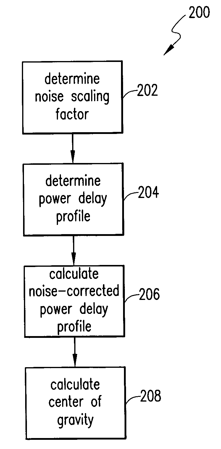
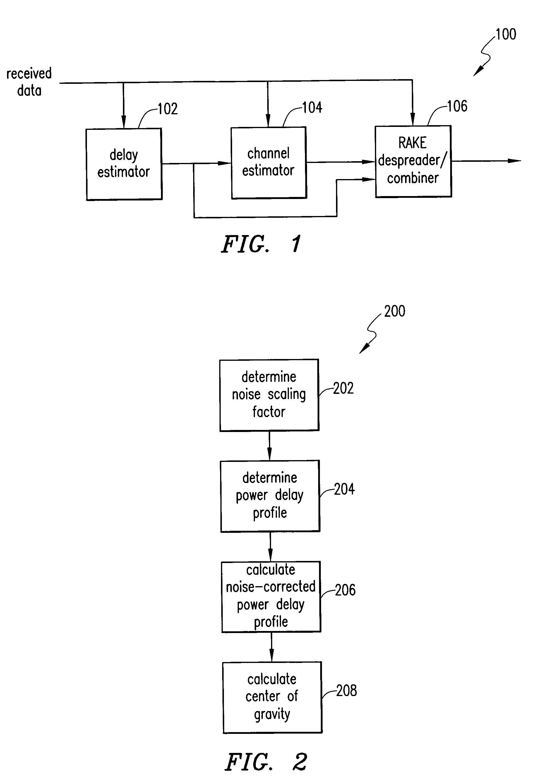
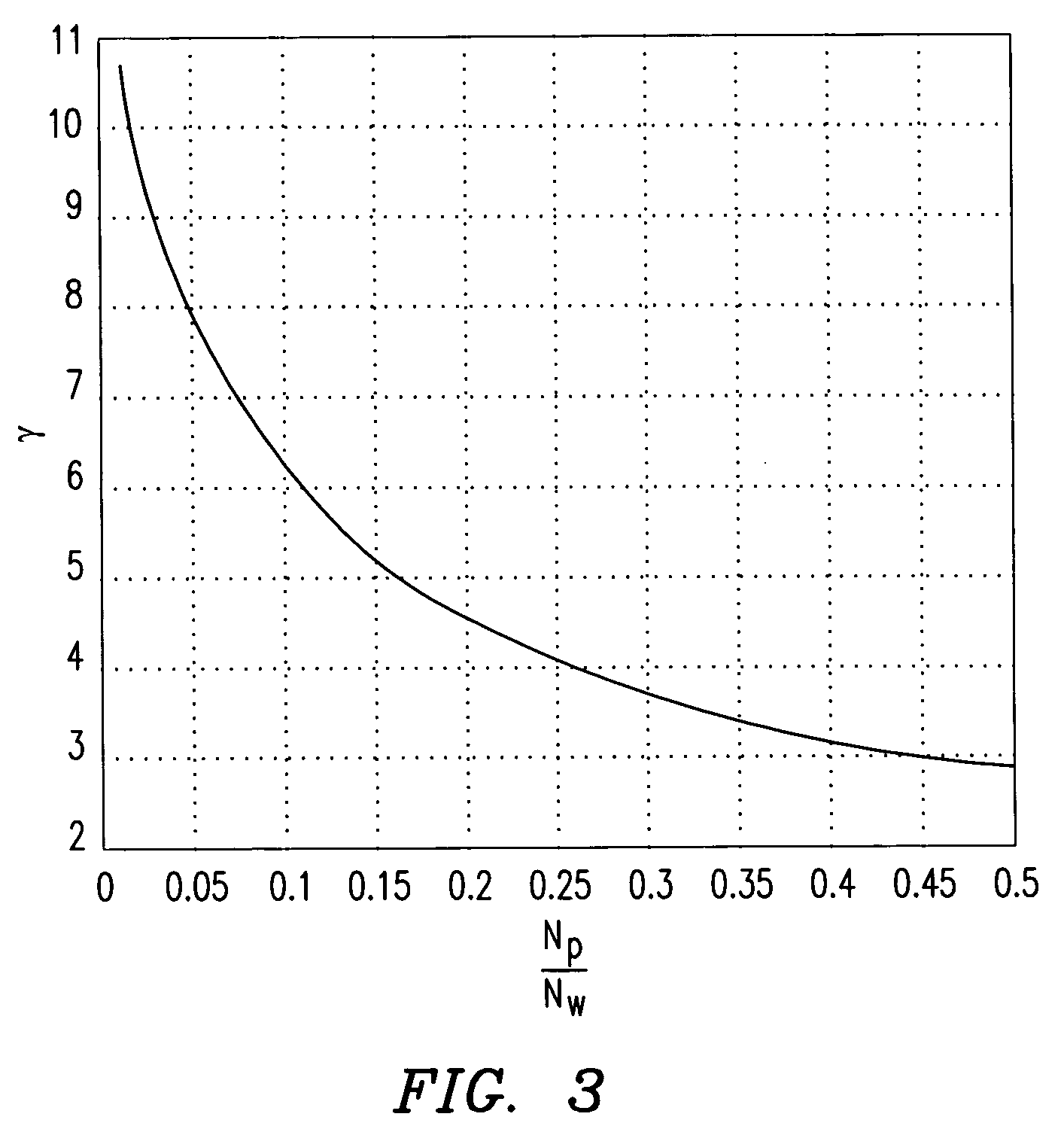
[0027]Embodiments of the invention permit an unbiased center-of-gravity position estimate to be calculated given a set of Nw power-delay-profile values. The center-of-gravity position estimate is computed from a subset of the power-delay-profile values. The subset may be, for example, the Np largest peaks. A noise floor component is removed from the Np peaks before the center-of-gravity position estimate is computed. A noise floor power is computed by averaging a subset of the power-delay-profile values. The subset of the power-delay-profile values may be, for example, the Nn smallest values. A noise-scaling factor γ is introduced into the center-of-gravity position estimate. The noise-scaling factor, which converts the biased noise floor power into an unbiased value, is computed based on a probability distribution of the noise component and on Nw, Np, and Nn. As a result, the computed center-of-gravity position estimate is substantially unbiased and the path-searcher window is posi...


PUM


Abstract

A method of determining a noise-corrected power delay profile includes determining a power delay profile and calculating a noise-corrected power delay profile. The step of calculating the noise-corrected power delay profile includes using a biased noise-floor power estimate, the power delay profile, and a noise-scaling factor.

Description

CROSS-REFERENCE TO RELATED APPLICATIONS[0001]This patent application incorporates by reference the entire disclosure of a U.S. patent application Ser. No. 10 / 755,803 entitled Method of and Apparatus for Path-searcher Window Positioning, Attorney Docket No. 53807-00075USPT and filed on the same date as this patent application.BACKGROUND[0002]1. Technical Field[0003]The invention relates to digital wireless communications systems in which delays of individual multi-path components of a time-varying fading channel are to be estimated. The digital wireless communications systems may include, for example, systems using Code Division Multiple Access (CDMA) RAKE receivers. The invention relates in particular to improving robustness of detection of new multi-path components in a radio propagation channel, as well as of tracking known paths, by reliably indicating a proper position for a path searcher window.[0004]2. History of Related Art[0005]In wireless communications, a physical channel ...

Claims


Application Information

Patent Timeline
Patent Type & Authority Patents(United States)
IPC IPC(8): H04B1/69
CPCH04B1/7113H04B1/7117
Inventor REIAL, ANDRES
Owner TELEFON AB LM ERICSSON (PUBL)
Why Eureka
Try Eureka