Head protecting airbag device

a technology for protecting the head and airbags, which is applied in the direction of threaded fasteners, screwdrivers, pedestrian/occupant safety arrangements, etc. it can solve the problems of reducing the strength of conventional clips, reducing the load of inserting the clips into the fixing slots, and causing the clip to fall off, so as to facilitate the handling of the airbag device, reduce the load of inserting the clips into the fixing slots, and facilitate the effect of handling the clip

Inactive Publication Date: 2008-05-20
TOYODA GOSEI CO LTD +1
View PDF14 Cites 73 Cited by
  • Summary
  • Abstract
  • Description
  • Claims
  • Application Information

AI Technical Summary

Benefits of technology

[0009]The present invention has been accomplished in order to solve the above problem. An object of the present invention is to provide a head protecting air bag device capable of easily attaching the attaching portions of an air bag to vehicle body with assured attaching stability.

Problems solved by technology

As a result, there is a fear that the clip comes off from the fixing slot.
Further, the conventional clip also gives a fear of strength reduction due to heat deterioration.
Thus, the conventional clip presented a problem to be solved about attaching an airbag to the vehicle body with assured stability.
However, if a material for the metallic clip is of a plate thickness that can be subject to bending, a part of the securing legs is likely to be bent when the air bag develops and expands like the clip of synthetic resin.
If it is bent, a fear of the clip coming off from the fixing slot occurs.
In this case, if the thickness is increased in order to prevent the bending, the load for inserting the clip into the fixing slot becomes too large.
As a result, the metallic clip having a large thickness will deteriorate the workability of mounting the air bag on the vehicle.

Method used


Image

  • Head protecting airbag device
  • Head protecting airbag device
  • Head protecting airbag device

Examples


Embodiment Construction

[0066]With reference to accompanying drawings, a description will be given of preferred embodiments of the present invention. However, the invention is not limited to the embodiments described herein. All modifications within the appended claims and equivalent relative thereto are intended to be encompassed in the scope of the claims.

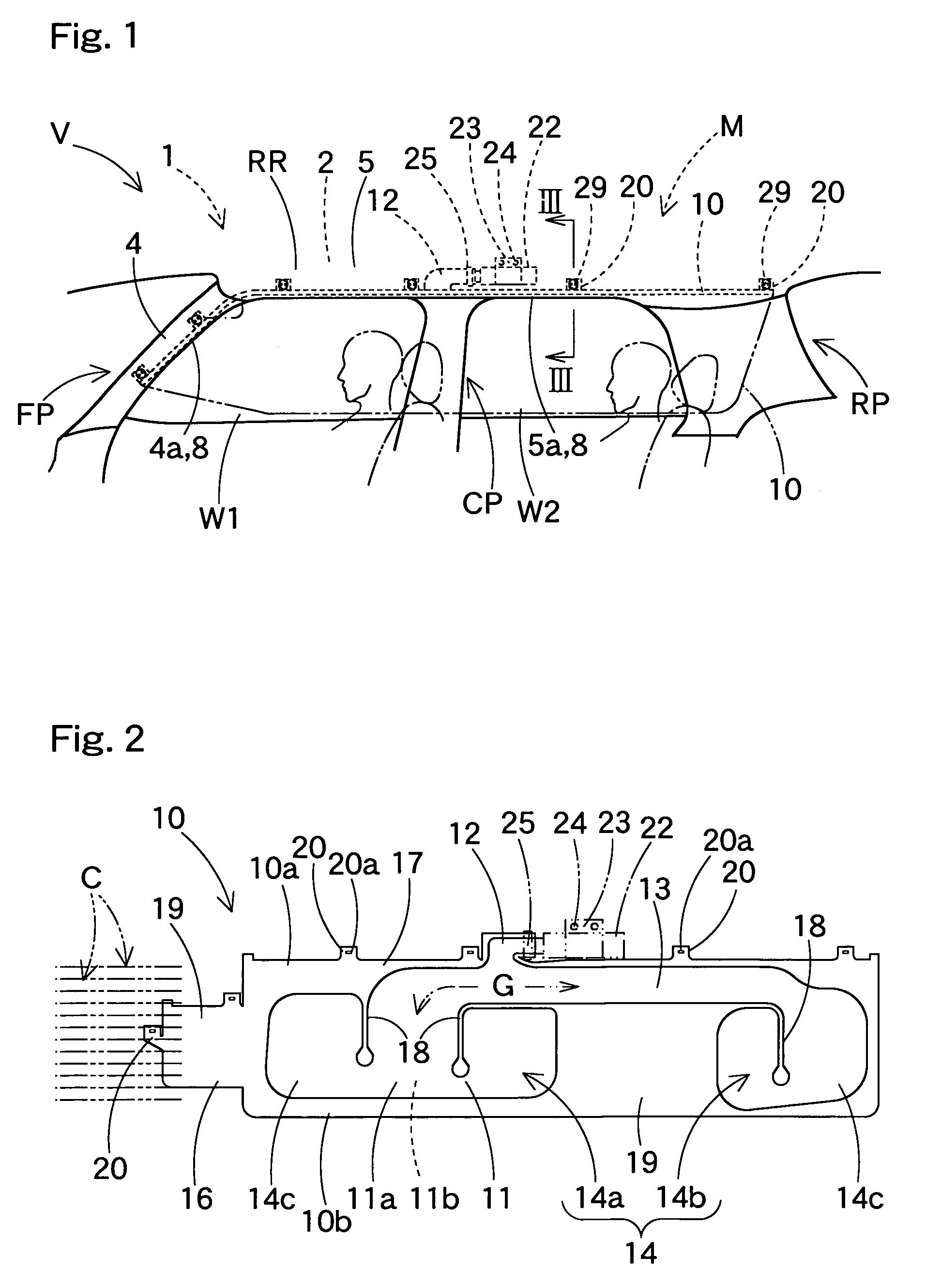
[0067]A head protecting air bag device M according to an embodiment of the present invention, as seen from FIG. 1, is mounted in a vehicle V, and includes an air bag 10, clips 29, an inflator 22, an attaching bracket 23 and an air bag cover 8. On the upper side of side windows W1, W2 inside the vehicle V, the air bag 10 is housed in a folded state within the range from the lower edge of a front pillar FP to the upper side of a rear pillar RP via the lower edge of a roof side rail RR.

[0068]The inflator 22, as seen from FIGS. 1 and 2, is generally cylindrical. A connection mouth 12 of the air bag 10 is mounted around the inflator 22 for taking in expansio...


PUM


Abstract

In a head protecting air bag device according to the present invention, a clip for attaching an attaching portion of an air bag to a fixing part on the side of a vehicle body includes a clip body and a locking part. The clip body has a shaft having a pair of securing legs protruded. The pair of securing legs are inserted in the fixing slot of the fixing part from an in-vehicle side via the attaching slot of the attaching portion and secured to the peripheral edge on an out-vehicle side of the fixing slot. The shaft is composed of a shell member of a metallic plate on the outer periphery and a core member of synthetic resin on the inner periphery. The core member is arranged on the opposite sides of a pair of securing lugs of the shell member. The core member has an inserting space in which a spacer of the locking part is inserted between the pair of securing lugs. The spacer limits the mutual approaching of the pair of securing legs. In the head protecting air bag according to this invention, using the clip, the attaching portion of the air bag can be easily attached to the vehicle body side with assured attaching stability.

Description

[0001]The present application claims priority from Japanese Patent Application No. 2004-280264 of Ikeda et al., filed on Sep. 27, 2004, the disclosure of which is hereby incorporated into the present application by reference.BACKGROUND OF THE INVENTION[0002]1. Field of the Invention[0003]The present invention relates to a head protecting airbag device provided with an air bag which develops and expands downward by expansion gas flowed in from the upper side of side windows inside a vehicle so that the head of a passenger can be protected.[0004]2. Description of Related Art[0005]Conventionally, in a head protecting air bag device, an air bag has been housed in the upper side of side windows, being folded in a state where its plural attaching portions are fixed to fixing part of vehicle body, and mounted in the vehicle. This air bag develops and expands to cover the side window when the expansion gas flows in.[0006]As a structure for attaching attaching portions of the air bag to the ...

Claims


Application Information

Patent Timeline
Patent Type & Authority Patents(United States)
IPC IPC(8): B60R21/20B60R21/213B60R21/217
CPCB60R21/213B60R21/232F16B5/065F16B19/1081F16B21/075F16B21/08Y10S411/903
Inventor IKEDA, TAKANOBUYAMAMOTO, TADASHIHAMAMOTO, YOJIYAJIMA, MASANORI
Owner TOYODA GOSEI CO LTD
Why Eureka
Try Eureka