Variable angle spinal screw assembly

a screw and variable angle technology, applied in the field of spinal screw assembly, can solve the problems of increasing the chance of cross-threading, torque exerted on the anchor, inadvertently introducing stress points along the rod, bending the rod or even loosening the threaded engagement of the anchor, etc., and achieve the effect of relieving the pressure of the cap

Active Publication Date: 2008-05-27
ALPHATEC SPINE INC
View PDF145 Cites 235 Cited by
  • Summary
  • Abstract
  • Description
  • Claims
  • Application Information

AI Technical Summary

Benefits of technology

The present invention is a spinal screw assembly that allows for adjustable securement of a stabilization rod between two vertebrae to effect internal fixation of the spine. The assembly includes a pedicle screw, a body member, and a locking cap. The body member is a cylindrical member that receives the head of the pedicle screw and allows for variable angular movement with respect to the screw. The body member also has slots to receive a portion of the fixation rod. The assembly is secured by pressing a locking cap against the fixation rod and the head of the pedicle screw. The technical effect of this invention is that it provides a secure and adjustable fixation of the spine across affected vertebrae.

Problems solved by technology

The present invention is a spinal screw assembly for internal fixation of the spine that solves the problems associated with conventional threaded fasteners. The technical problem addressed is the difficulty and access limitations during surgical implantation of spinal stabilization systems, which can result in cross-threading and torquing on the anchor or rod. The invention provides an extended range of motion, allowing the surgeon additional freedom in locating the screws and reducing the requirement for rod contouring. It also eliminates the problems associated with threaded fasteners and provides a significantly improved variable angle spinal screw assembly.

Method used


Image

  • Variable angle spinal screw assembly
  • Variable angle spinal screw assembly
  • Variable angle spinal screw assembly

Examples


Embodiment Construction

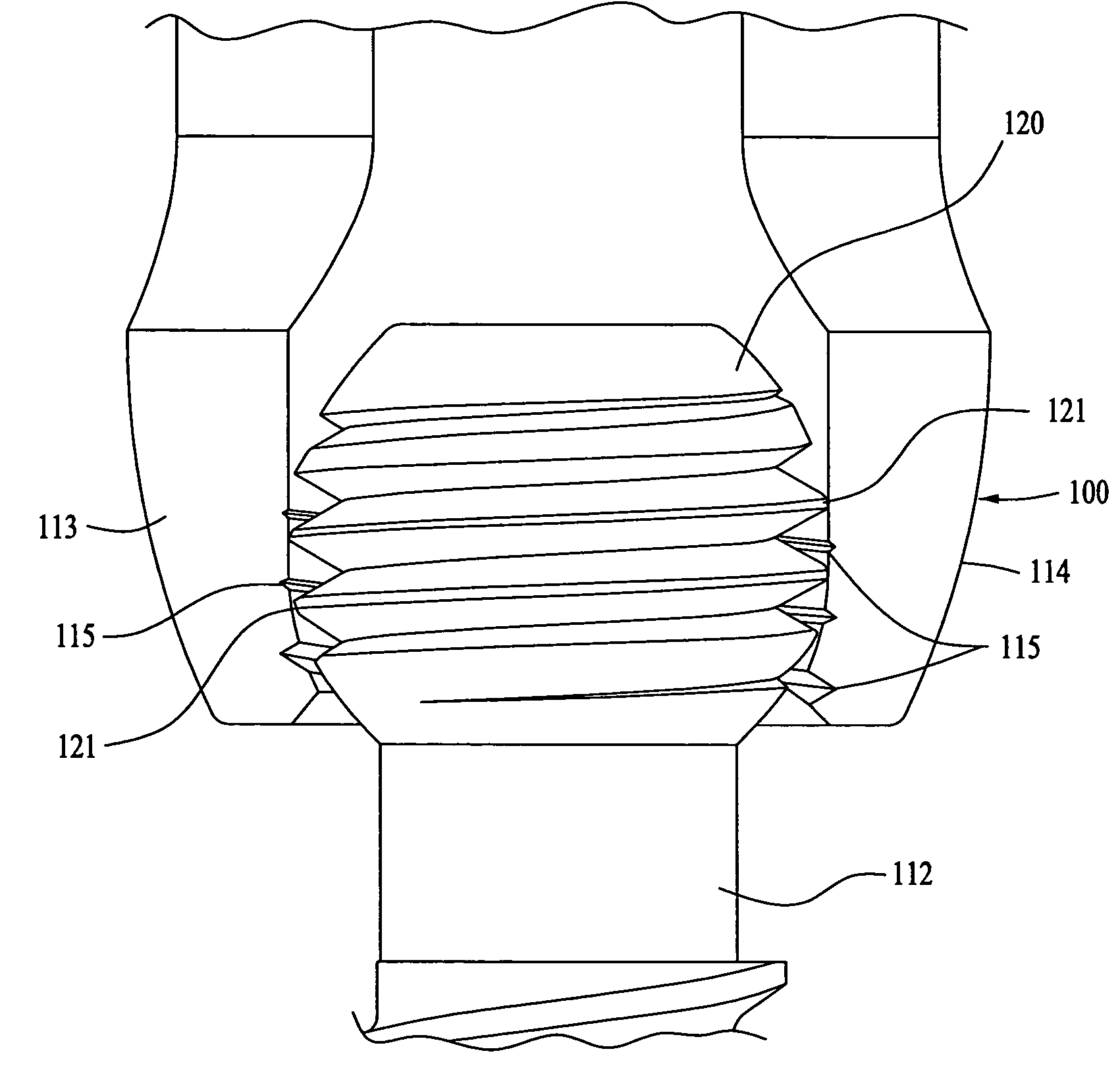
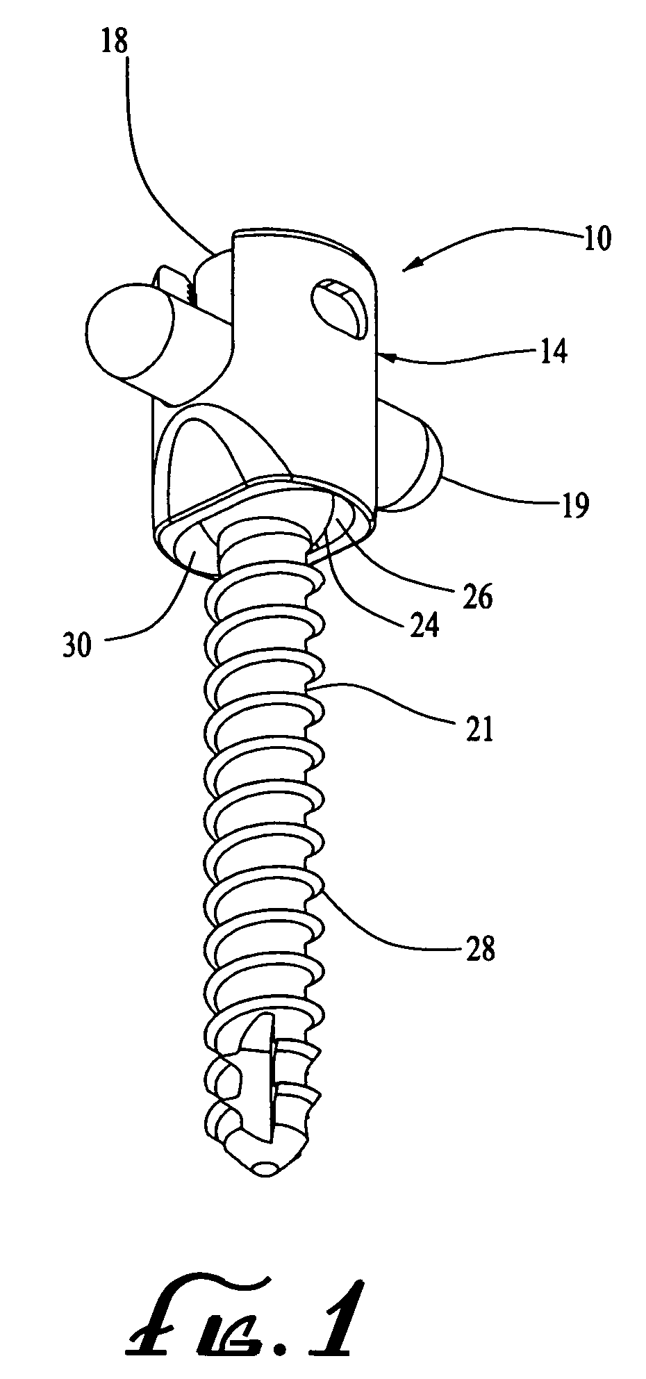
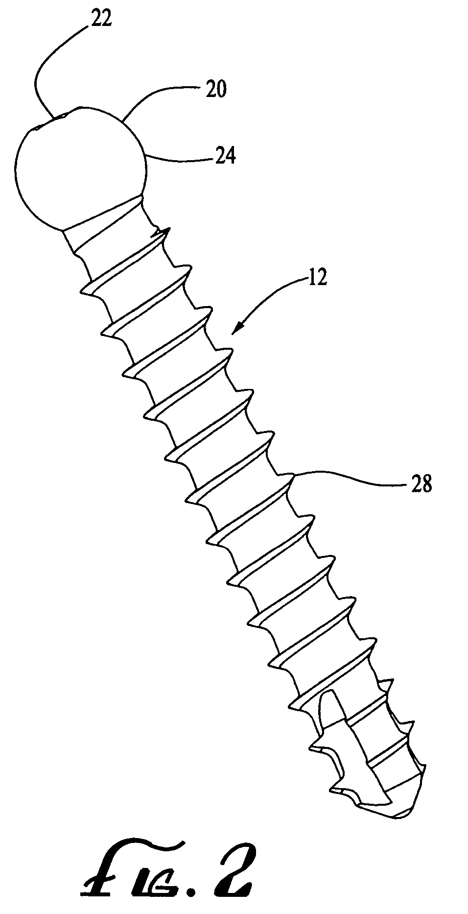
[0029]Referring now in detail to the drawings, the variable angle spinal screw assembly 10 of the present invention comprises a pedicle screw 12, a body member 14, a bushing 16 and a locking cap 18. The assembly 10 is used with at least one other such assembly and a stabilization or fixation rod 19 to connect the assemblies and stabilize the vertebras into which the assemblies are inserted. The pedicle screw 12 preferably employed in assembly 10 has a spherical head 20 defining a slot 22 therein used to drive the screw into the bone. The rounded surface 24 defined by the lower portion of screw head 20 rests upon and mates with a rounded interior surface 26 formed in the inner or lower end of the body member 14 of the assembly 10 so as to form a modified ball joint that provides the desired variable angular movement of the body member with respect to the embedded pedicle screw. The threaded shaft portion 28 of screw 12 extends therefrom through the opening 30 in the lower end of body...


PUM


Abstract

A spinal screw assembly providing an adjustable securement of a fixation rod across at least two vertebrae. The assembly includes a pedicle screw having a spherical head portion, a threaded shaft portion and a tool engagement surface in the head portion for use in driving the screw into a vertebrae. The head portion of the screw is positioned in a body member adjacent a curvilinear surface disposed about an aperture in the end of the body member such that the shaft portion of the screw extends therethrough and the curvilinear inner surface abuts and mates with the head portion of the screw so as to define a ball joint therewith. The body member additionally defines a pair of opposed parallel slots therein adapted to receive a portion of the fixation rod and a locking cap bears against the fixation rod to releasably secure the rod within the assembly.

Description


Claims


Application Information

Patent Timeline
Owner ALPHATEC SPINE INC
Why Eureka
Try Eureka