Unlock instant, AI-driven research and patent intelligence for your innovation.

Power connector

Inactive Publication Date: 2008-06-17
CHENG UEI PRECISION IND CO LTD
View PDF7 Cites 12 Cited by
  • Summary
  • Abstract
  • Description
  • Claims
  • Application Information

AI Technical Summary

Benefits of technology

[0007]As described above, the propping portions of the conductive contact is secured in the groove by against the propping beam, which prevents the conductive contact from rotating and moving in the main body, and ensures the conductive contact being fastened firmly and securely. Therefore, the affection of a pushing / pulling force between the conductive contact and a terminal of a mating connector on the secure retention of the conductive contact in the main body is decreased or even eliminated. Thereby, a steady transmission of the electrical signal is achieved.

Problems solved by technology

With the increase of the number of the components, the problems will increase too, for example, the housing looses from the main body, and then causes the unstable engagement between the conductive contact and the main body, therefore, the electrical signal is unsteadily transmitted.

Method used


Image

  • Power connector
  • Power connector
  • Power connector

Examples


Embodiment Construction

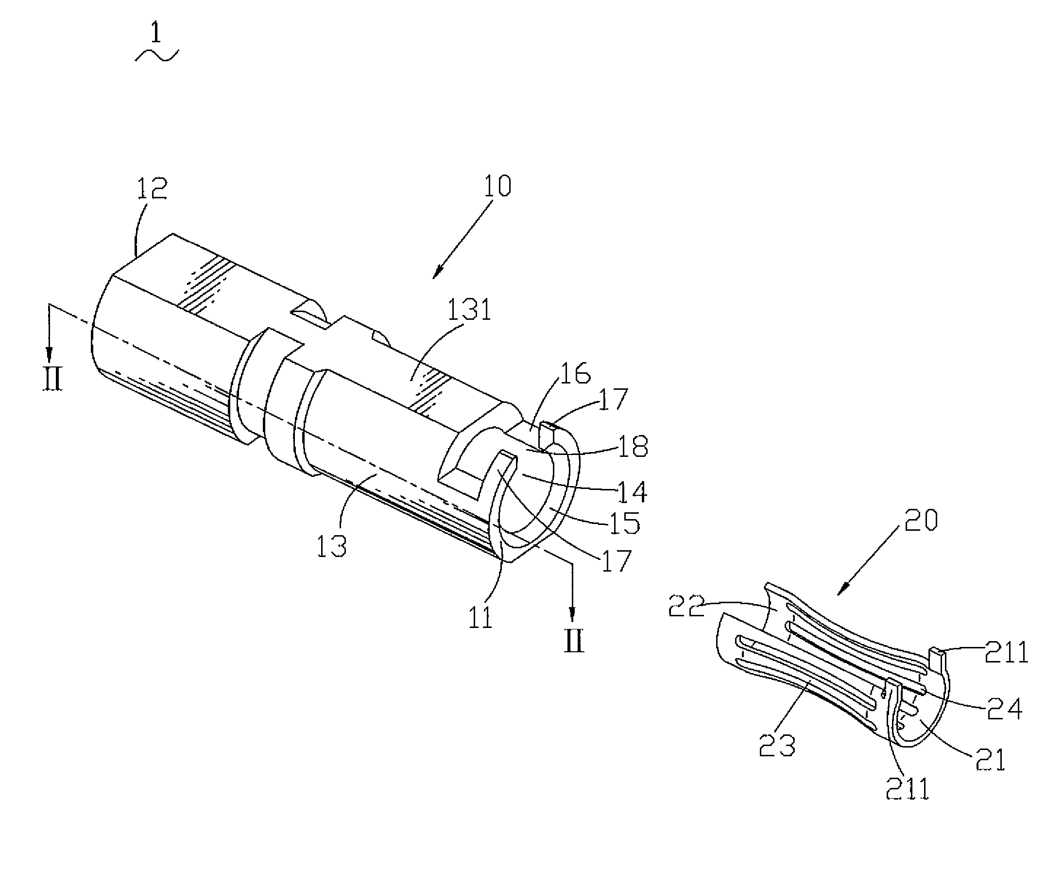
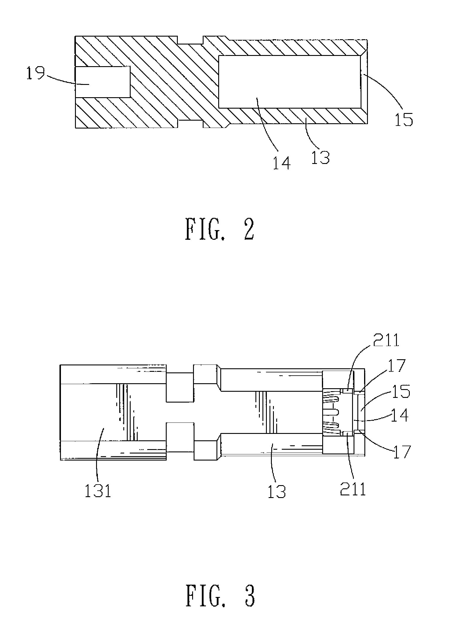
[0013]With reference to FIG. 1 and FIG. 2, a power connector 1 of the present invention comprises a main body 10 and a conductive contact 20 received in the main body 10. The main body 10 is about cylinder-shaped, having a front surface 11, a back surface 12 and a sidewall 13. A receiving cavity 14 is opened in the main body 10 from the front surface 11 to the middle part of the main body 10. There is a guiding portion 15 defined at the front of the receiving cavity 14. The guiding portion 15 is a trumpet shape and connects with the front surface 11. Two parallel positioning surfaces 131 are defined at the top and the bottom of the sidewall 13. A groove 16 is defined vertically to the positioning surface 131 in the front of the positioning surface 131. The groove 16 communicates with the receiving cavity 14 at the top, and is shallow than the middle of the receiving cavity 14, then a propping beam 17 is formed at the front of the groove 16. A gap 18 is opened in the middle part of t...


PUM


Abstract

A power connector includes a main body and a conductive contact. The main body has a front surface and a sidewall. The front surface defines a receiving cavity. The front of the sidewall defines a groove communicating with the receiving cavity at the top, then a propping beam is formed at the front of the groove. The propping beam defines a gap communicating with the receiving cavity. The gap communicates with the groove at back and communicates with the outside at front. The conductive contact is received in the receiving cavity of the main body, having a fixing portion, a base portion and connecting portions connecting the fixing and base portions. The fixing portion is formed an arch structure, then an opening end is formed at the top. A propping portion is projected from the fixing portion. The propping portion is secured in the groove by against the propping beam. Therefore, the conductive contact can be fastened firmly and securely.

Description

BACKGROUND OF THE INVENTION[0001]1. Field of the Invention[0002]The present invention relates to a power connector, and more particularly to a power connector with a conductive contact fastened firmly and securely.[0003]2. The Related Art[0004]Power connectors are widely used in the field of electronics. A conventional power connector comprises a main body and a conductive contact received in the main body. In order to transmit an electrical signal steadily, it's necessary to ensure a certain pressing force between the conductive contact and a terminal of a mating power connector while the mating power connector is engaging with the conductive contact. Because of the pressing force, a pushing / pulling force between the conductive contact and the terminal of the mating connector arises when the mating connector is inserted into or drawn out of the power connector, and the pushing / pulling force will make the conductive contact move forwards or backwards and affect the secure retention ...

Claims


Application Information

Patent Timeline
IPC IPC(8): H01R9/05
CPCH01R13/187H01R13/111
Inventor MAO, HU-QING
Owner CHENG UEI PRECISION IND CO LTD