Vehicular battery mounting structure

a technology for mounting structures and electric appliances, which is applied in the direction of cell components, electrochemical generators, cell component details, etc., can solve the problems of severe restrictions on the dimension in the vertical direction of the under seat space, the height of the battery pack becomes great, and the foregoing battery mounting structure has problems. , to achieve the effect of simple structure of cooling passageways

Active Publication Date: 2008-09-16
TOYOTA JIDOSHA KK
View PDF22 Cites 64 Cited by
  • Summary
  • Abstract
  • Description
  • Claims
  • Application Information

AI Technical Summary

Benefits of technology

[0011]According to this mounting structure, since the battery cells or the battery modules are stacked in the longitudinal direction relative to the vehicle, the cooling medium can be caused to flow, for example, from a center side to an outward side in the direction of width of the vehicle. This structure eliminates the need for provision of a chamber in an upper or lower portion of a battery pack, and therefore allows a reduction in the height of the battery pack in the vertical direction. Therefore, the battery pack can be mounted easily even if there are severe restrictions regarding the vertical dimensions of an installation space as in the case of an under-seat space.
[0012]It is preferable that the seat be a seat that does not have a power seat function. In this preferable structure, no electrical equipment component part for realizing a power seat function is provided in the space under or below the seat in which the battery pack is disposed, so that the mountability of the battery pack improves.
[0013]Furthermore, it is preferable that the seat be a passenger seat or a rear seat. Therefore, the battery pack is disposed under or below a rear seat or a passenger seat, that is, a seat that is less often equipped with a power seat function. Since no electrical equipment component part for realizing a power seat function is provided in the space under or below the passenger or rear seat in which the battery pack is disposed, the mountability of the battery pack improves. Furthermore, since the steering wheel is not present forward of passenger and rear seats, the passenger and rear seats can be easily moved, and are therefore advantageous for easy maintenance of the battery pack.
[0017]Furthermore, the cooling fan may supply the cooling medium from the side that faces the center line of the width of the vehicle to the side opposite from the side that faces the center line of the width of the vehicle, and may discharge the cooling medium into a cabin. This structure makes it possible to cool the battery pack by circulating temperature-controlled air from the cabin through the battery pack via the cooling fan.
[0020]It is also possible that a suction direction of the cooling fan be a direction of a rotating axis of the cooling fan, and a discharge direction of the cooling fan be a circumferential direction relative to the cooling fan. Since the cooling fan with its suction direction being along the rotating axis and its discharge direction being circumferential, the cooling fan has a reduced dimension in the direction of the width of the vehicle, and can easily be incorporated into the battery pack. Therefore, a compact battery pack can be realized.
[0021]The cooling fan may be a sirocco fan. Since a sirocco fan is compact in size and able to generate great pressure, the employment thereof will achieve efficient conveyance of the cooling air even if the cooling passageways have a complicated configuration and therefore cause great pressure loss.

Problems solved by technology

However, the foregoing battery mounting structure has problems as stated below.
Therefore, the height of the battery pack is becomes great.
However, the under-seat space has severe restrictions on the dimension in the vertical direction.
Therefore, the containment of a battery within the under-seat space is not easy.
Furthermore, since the inlet and outlet ducts for the battery are formed by using a vehicle body member, the structure becomes complicated.

Method used


Image

  • Vehicular battery mounting structure
  • Vehicular battery mounting structure
  • Vehicular battery mounting structure

Examples


Embodiment Construction

[0031]In the following description, the present invention will be described in more detail in terms of exemplary embodiments.

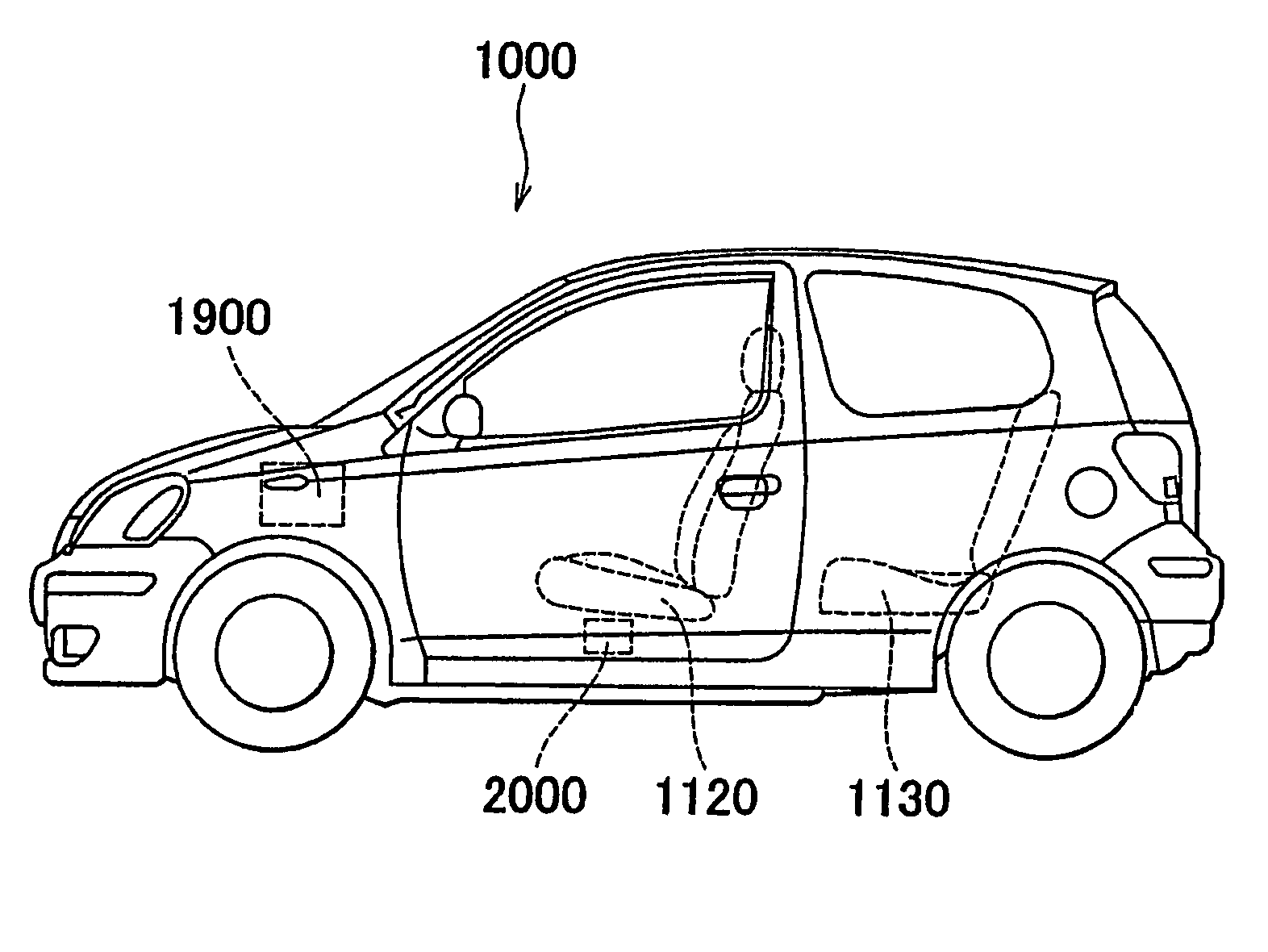
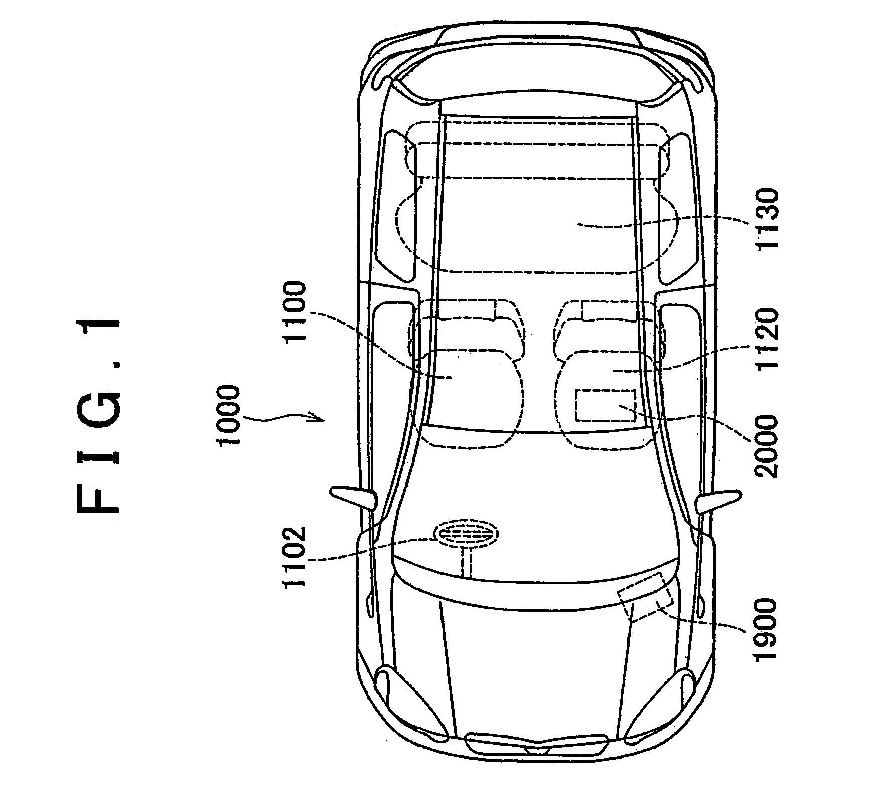
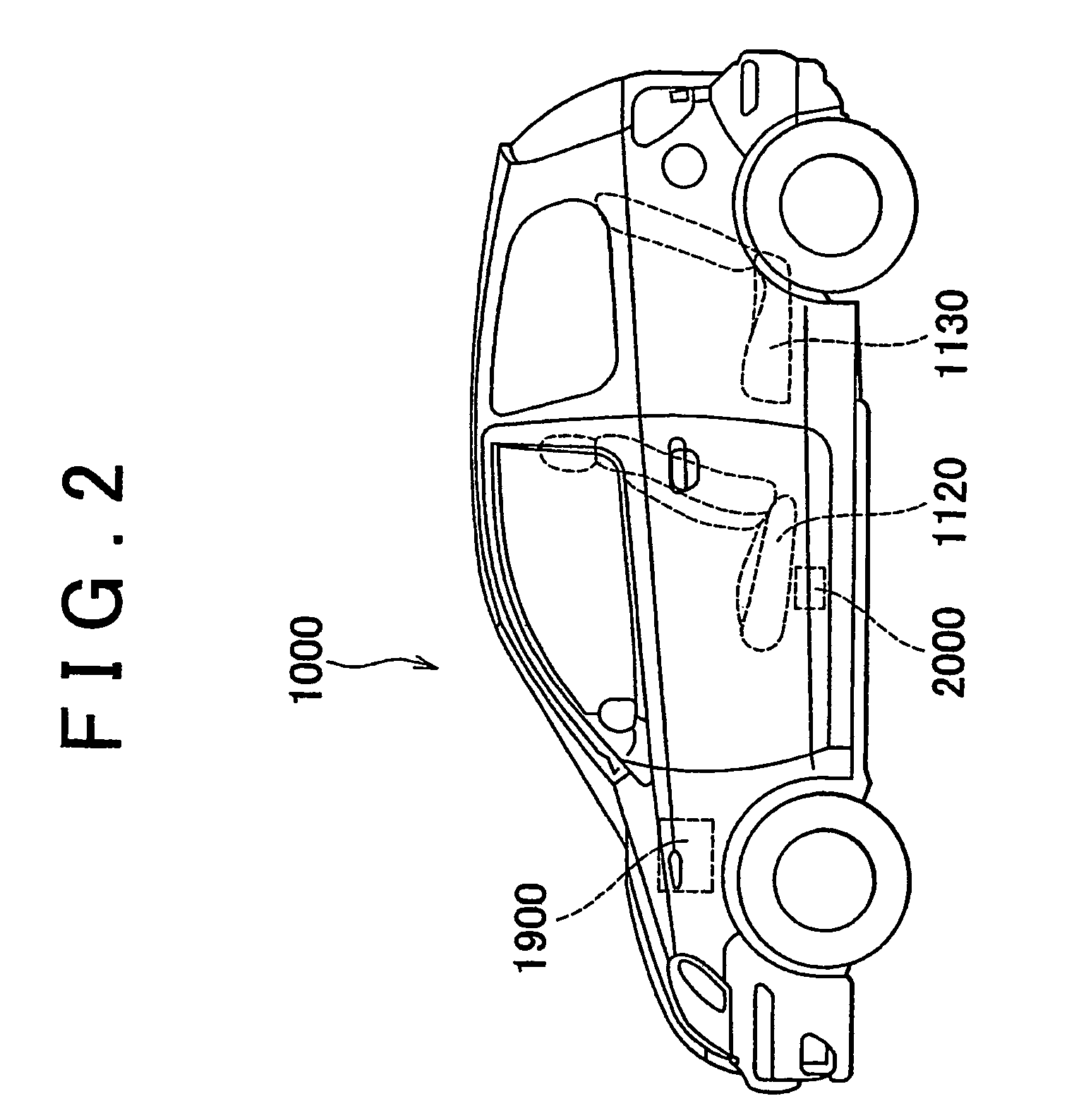
[0032]With reference to FIGS. 1 and 2, a vehicle 1000 in which a battery pack is mounted through the use of a battery pack mounting structure in accordance with the invention will be described. FIG. 1 shows a top plan view of the vehicle 1000. FIG. 2 shows a side view of the vehicle 1000.

[0033]The vehicle 1000 has an automatic transmission. Furthermore, the vehicle 1000 incorporates an idling stop system (also termed “stop-and-go system”) that automatically stops the engine if a driver depresses a brake pedal after the vehicle has stopped at the red light at an intersection or the like, and that automatically restarts the engine when the driver discontinues depressing the brake pedal and depresses an accelerator pedal. During the idling stop of such a vehicle, no power is supplied from the engine for operating an oil pump of the automatic transmission (e.g., a...


PUM

PropertyMeasurementUnit
voltageaaaaaaaaaa
widthaaaaaaaaaa
poweraaaaaaaaaa

Abstract

A vehicular battery mounting structure for mounting a battery pack above a floor panel while securing a simple structure of cooling passageways. This battery mounting structure is suitably adopted in a vehicle that is equipped with a first battery pack and a second battery pack that has stricter requirements regarding the temperature of the service environment. The first battery pack is mounted in an engine compartment. The second battery pack is disposed below a seat that is mounted on a floor panel as a seat for a vehicle occupant other than a driver. Specifically, a plurality of battery cells of the second battery pack are stacked in the longitudinal direction relative to the vehicle. Cooling passageways are provided between the battery cells, and conduct air supplied by a sirocco fan from a center side to an outer side in the direction of width of the vehicle.

Description

[0001]This is a 371 national phase application of PCT / IB2004 / 000248 filled 03 Feb. 2004, claiming priority to Japanese Application No. 2003-027183 filed 04 Feb. 2003, the contents of which are incorporated herein by reference.BACKGROUND OF THE INVENTION[0002]1. Field of the Invention[0003]The invention relates to a mounting structure for an electric appliance mounted in a vehicle and, more particularly, to a vehicular battery mounting structure in which a battery pack is mounted on a floor panel of a vehicle.[0004]2. Description of the Related Art[0005]In order to achieve improved fuel economy and clean exhaust gas, the development of vehicles having new driving mechanisms, such as electric vehicles, hybrid vehicles, etc., has been pursued. Such vehicles need to be equipped with electric appliances that are not provided in the vehicles that have an internal combustion engine as a sole vehicle driving power source. Examples of such electric appliances include a traction motor of an e...

Claims


Application Information

Patent Timeline
Patent Type & Authority Patents(United States)
IPC IPC(8): B60K11/00B60K1/00B60R16/04B60K1/04B60R16/02H01M10/60H01M10/613H01M10/617H01M10/625H01M10/647H01M10/6557H01M10/6563H01M50/204H01M50/244H01M50/249
CPCB60R16/04H01M2/1083H01M10/5067H01M10/5016H01M10/5059H01M10/5004B60K1/04H01M10/625H01M10/6563H01M10/6557H01M10/613Y02E60/10H01M50/204H01M50/249H01M50/244B60K2001/005B60K2001/0422B60K2001/0433
Inventor TSUCHIYA, TAKENORI
Owner TOYOTA JIDOSHA KK
Why Eureka
Try Eureka