Sensing system based on multiple resonant electromagnetic cavities

a sensing system and cavity technology, applied in the field of wireless sensing system and method for measuring the properties of materials and structures based on electromagnetic resonance, can solve the problems of increasing structural deficiencies, deterioration and increasing structural deficiencies, installation and ongoing use of these sensors, etc., and the cost of installation and preparation of the site for monitoring equipment can easily equal the cost of sensors and interrogation equipmen

Active Publication Date: 2008-10-28
SMART AUTONOMOUS SOLUTIONS
View PDF36 Cites 8 Cited by
  • Summary
  • Abstract
  • Description
  • Claims
  • Application Information

AI Technical Summary

Benefits of technology

[0014]Each sensor is formed by one or more electromagnetic resonant cavity such as, for example, an electromagnetic cavity having a resonant frequency that is related to the dimensions of the cavity. The dimensions of the cavity are dependant upon the strain experienced by the structure. Accordingly, strain experienced by the structure would be represented by changes in the resonant frequency of the sensor. The interrogator utilizes an interrogation signal having a frequency content that matches the resonant frequency of the electromagnetic cavity. Upon excitation by the interrogation signal, the electromagnetic cavity would produce a response signal that is related to the resonant frequency of the cavity. The interrogator would process the response signal to determine the strain that is experienced by the structure. However, the dimensions of the cavity can also be influenced by other factors such as, for example, but not limited to, temperature. Most metals will expand in dimension as the temperature increases. By using two or more cavities simultaneously it is possible to distinguish between the effects of strain and temperature and therefore more accurately determine the value of multiple parameters. For example, but not limited to, by using two cavities it is possible to measure moisture, while accurately compensating for the effects of temperature.

Problems solved by technology

The increased weight and numbers of today's trucks compared with design loads that were used for the roads and bridges at the time of construction, combined with aging, environmental conditions and the use of corrosive salts has resulted in deterioration and increasing structural deficiencies.
This causes problems in the installation and ongoing use of these sensors.
Several cases have shown that the cost of installation and preparation of site for monitoring equipment can easily equal the cost of sensors and interrogation equipment.
Therefore, not all sites will justify the cost of installation and maintenance of a permanent site.
The disadvantage is that this type of sensor requires significant additional electronics, and hence additional cost, for measurement and communications.
One drawback of this type is that it must contain its own power source.

Method used


Image

  • Sensing system based on multiple resonant electromagnetic cavities
  • Sensing system based on multiple resonant electromagnetic cavities
  • Sensing system based on multiple resonant electromagnetic cavities

Examples


Embodiment Construction

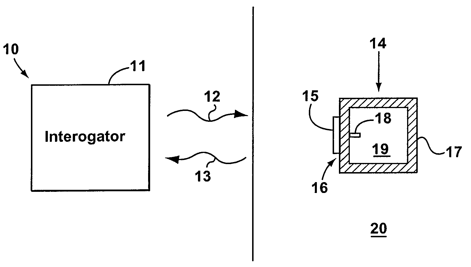
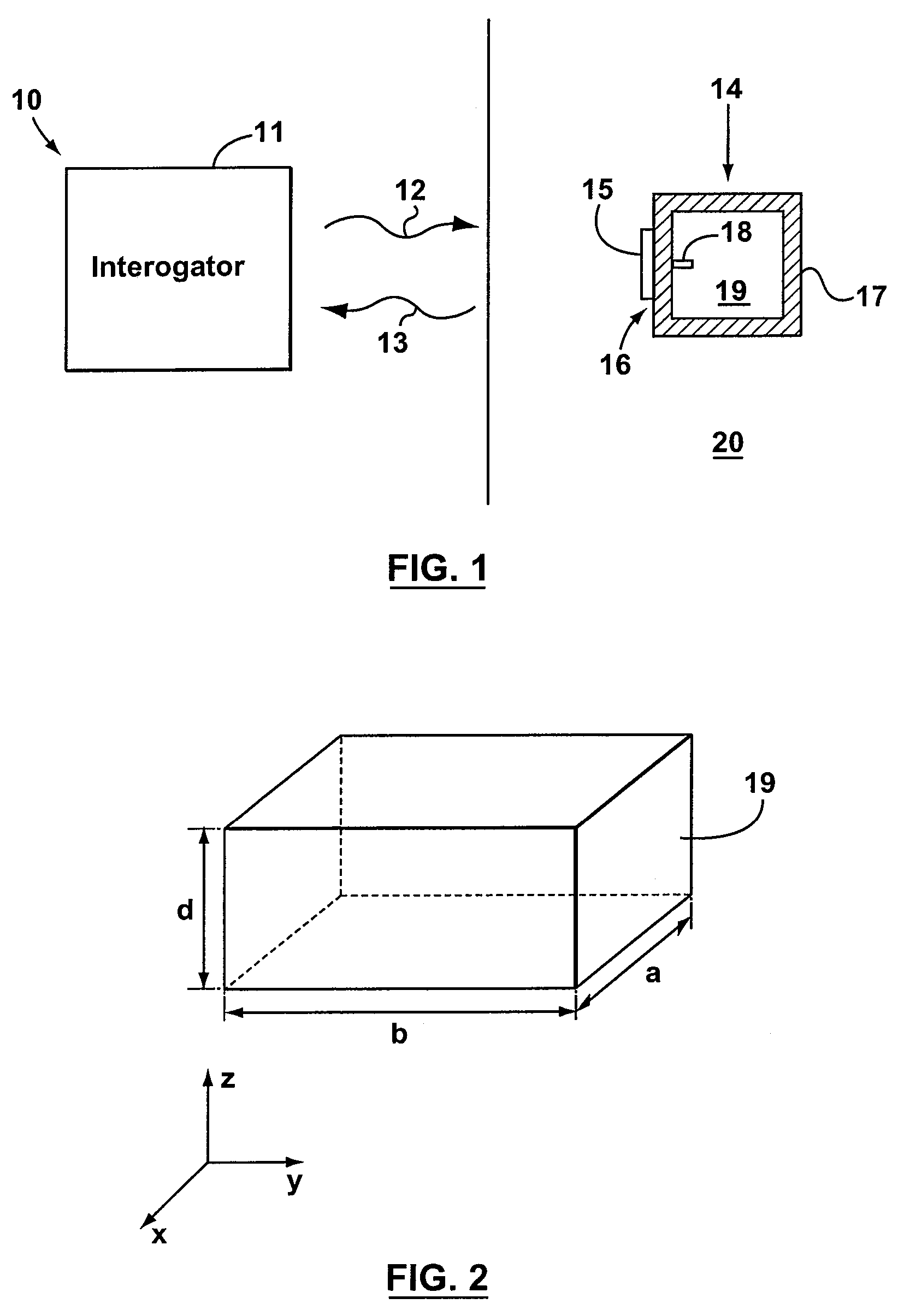
[0049]Referring now to FIG. 1, shown therein is a partial cross-sectional front view of a resonant cavity sensing system 10 for determining or measuring parameters 14 experienced by a structure 20. The sensing system 10 comprises an interrogator 11 and a plurality of sensors 17. The structure 20 could be for example, but not limited to, a bridge, a road, an overpass, a building, an aircraft or the like and the parameters 14 can include, but are not limited to, strain, temperature, moisture level, pH or pressure. The integrity of the structure 20 could be monitored at any given time to indicate when repair or replacement is necessary for the structure 20. To achieve this, several sensors 17 would be strategically placed at various locations of the structure 20 that are susceptible to strain (these locations are known to those skilled in the art). For simplicity of illustration and explanation only one sensor 17 and only a partial view of the structure 20 is shown in FIG. 1. The senso...


PUM

PropertyMeasurementUnit
speedaaaaaaaaaa
frequencyaaaaaaaaaa
frequencyaaaaaaaaaa

Abstract

A system and a method for measuring properties and health of structures are disclosed. The system comprises a number of sensors connected to a single antenna. Each sensor has a body that defines an electromagnetic resonator. The electromagnetic resonator produces a response signal in response to an interrogation signal. The body is coupled to the structure to so as to allow the parameters of interest alter the resonance properties of the electromagnetic resonators thereby altering the response signal. The sensor further includes a coupler that is coupled to the body. The coupler transfers the interrogation signal into the electromagnetic resonator and transfers the response signal from the electromagnetic resonator. The system further includes an interrogator that generates and transmits the interrogation signal to the sensor. The interrogator also receives the response signal.

Description

[0001]This application claims the benefit of U.S. Provisional Application No. 60 / 719,584, filed Sep. 23, 2005, the entire contents of which is hereby incorporated by reference.[0002]The section headings used herein are for organizational purposes only and are not to be construed as limiting the subject matter described in any way.FIELD[0003]Applicants' teachings are related to a system and method for measuring the properties of materials and structures. More particularly, the applicants' teachings are directed towards a wireless sensing system and method for measuring the properties of materials and structures based on electromagnetic resonance.INTRODUCTION[0004]In the 1930's the U.S. and Canadian governments began public work programs to develop a transportation infrastructure comprising roadways and bridges. The increased weight and numbers of today's trucks compared with design loads that were used for the roads and bridges at the time of construction, combined with aging, enviro...

Claims


Application Information

Patent Timeline
Patent Type & Authority Patents(United States)
IPC IPC(8): G01B7/16G01L1/00G01M99/00
CPCG01M5/0008G01M5/0033G01M5/0091
Inventor FALLAH-RAD, MEHRANTHOMSON, DOUGLAS JOHNBRIDGES, GREGORY ERNEST JOHNSHAFAI, LOTFOLLAH
Owner SMART AUTONOMOUS SOLUTIONS
Why Eureka
Try Eureka