Dual hinge recess weatherproof electrical box assembly

a technology of electrical boxes and recesses, which is applied in the installation of lighting conductors, electrical apparatus casings/cabinets/drawers, and coupling device connections

Inactive Publication Date: 2008-12-09
THOMAS & BETTS INT INC
View PDF36 Cites 53 Cited by
  • Summary
  • Abstract
  • Description
  • Claims
  • Application Information

AI Technical Summary

Problems solved by technology

Although some of these assemblies include a cover that can operate to inhibit some moisture from entering the box and causing damage, moisture remains a problem in that the electronic components are positioned adjacent the face plate.

Method used


Image

  • Dual hinge recess weatherproof electrical box assembly
  • Dual hinge recess weatherproof electrical box assembly
  • Dual hinge recess weatherproof electrical box assembly

Examples


Embodiment Construction

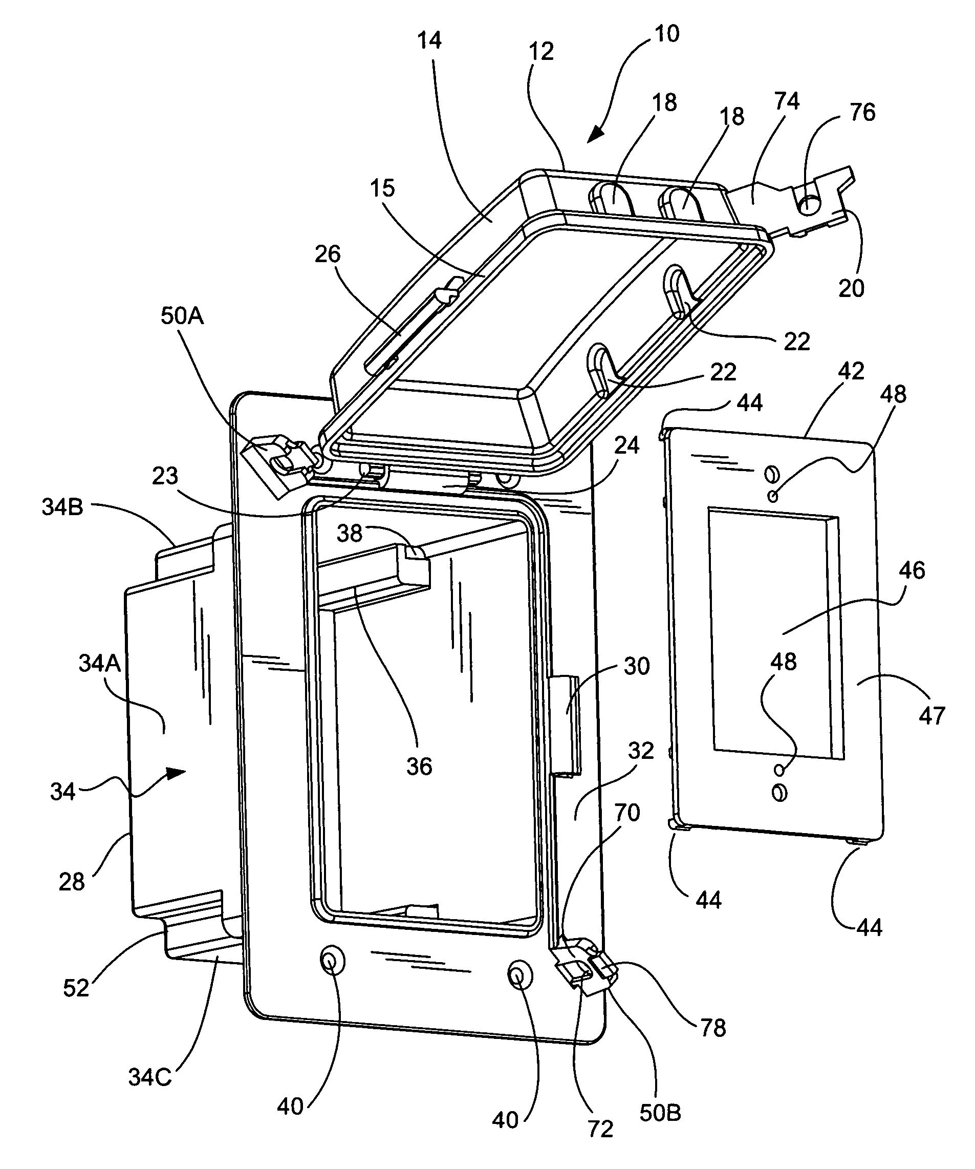
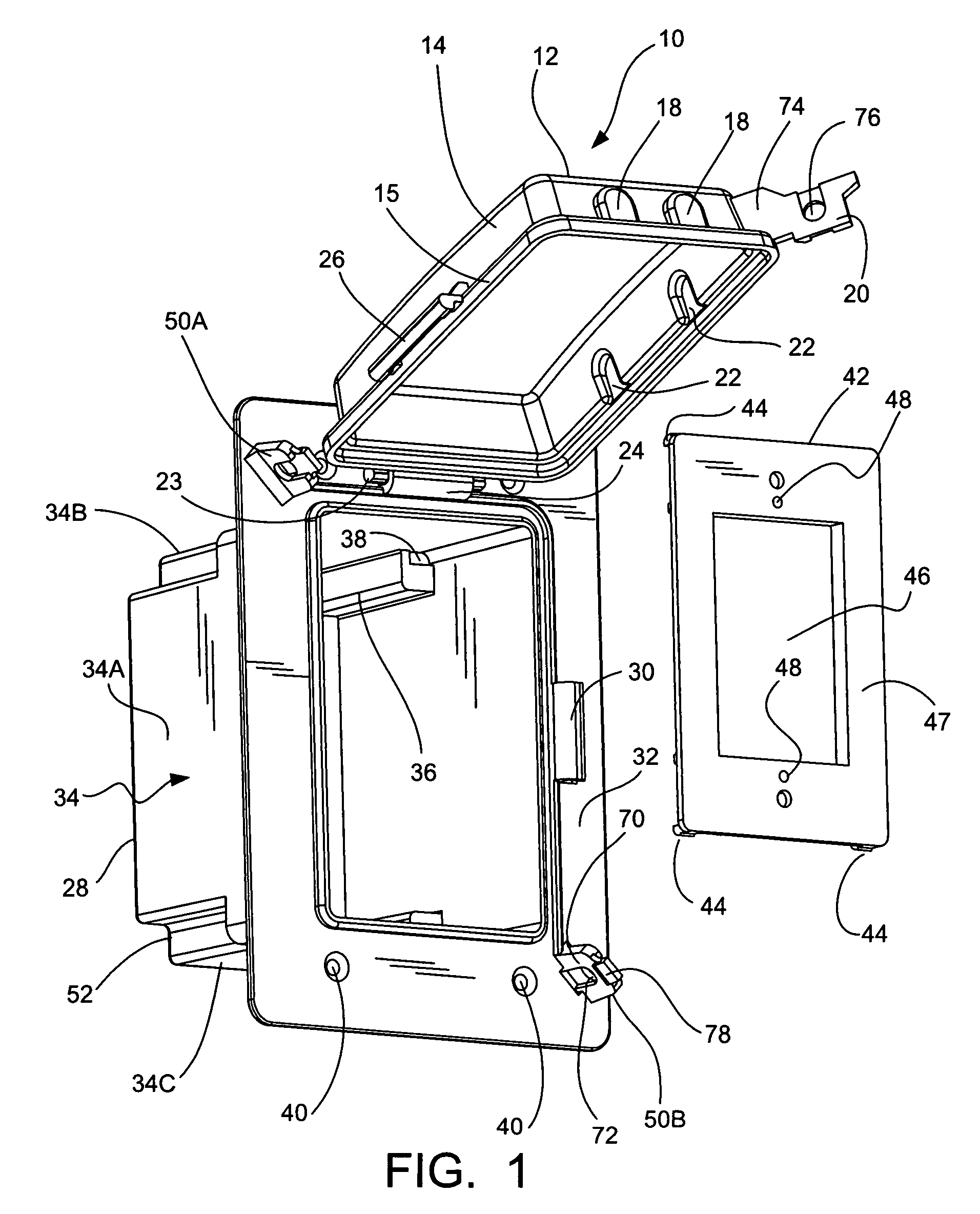
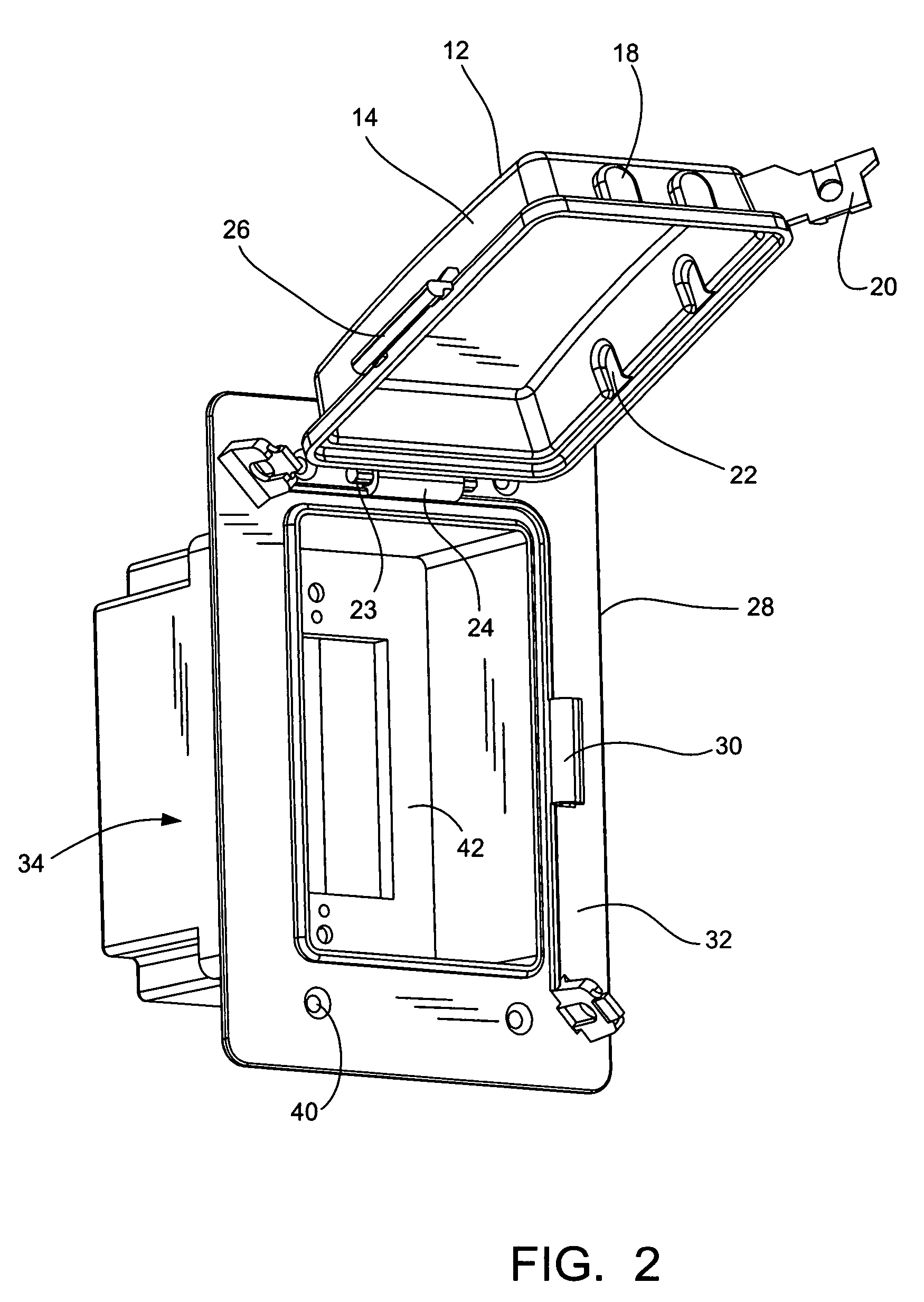
[0018]Referring now to FIGS. 1-6, an electrical box assembly 10 according to the present invention is disclosed. The electrical box assembly 10 includes an electrical connector box 28 having a face plate 32 attached thereto, a box cover 12 removably attached to the face plate 32, and an adapter plate 42 that is removably secured to a recessed inside portion of the electrical connector box 28.

[0019]The electrical connector box 28 of the present invention is a generally rectangular box-like member that includes a generally flat backwall 29 (see FIG. 6) with a continuous sidewall member (indicated generally at 34) upstanding therefrom. The sidewall member 34 includes a pair of oppositely disposed endwall portions 34B, 34C and a pair of oppositely disposed sidewall portions 34A, 34D. The front edges of the endwall portions 34B, 34C and sidewall portions 34A, 34D preferably define a generally planar open front for the electrical connector box 28.

[0020]As shown in FIG. 6, the back wall 29...


PUM


Abstract

The present invention concerns a dual hinge recess weatherproof outdoor electrical box assembly for shielding and protecting electrical components from moisture. The electrical box assembly includes an electrical box having a plurality of hinge sockets, an adapter plate that is recessed in the electrical box, and a cover having a plurality of hinge pins for operable engagement with the hinge sockets.

Description

CROSS-REFERENCE TO RELATED APPLICATIONS[0001]This application claims the benefit of U.S. Provisional Application No. 60 / 858,978 filed Nov. 14, 2006, the contents all of which are incorporated herein by reference.FIELD OF THE INVENTION[0002]The present invention generally relates to a hinged electrical box assembly, and more particularly to a dual hinge weatherproof electrical box assembly.BACKGROUND OF THE INVENTION[0003]Generally, electrical box assemblies are used for a variety of applications and provide a termination point for electrical wires for connection to an electrical component. Depending on the application and location, electrical box assemblies can be mounted on or in a wall in either a horizontal or vertical orientation. Once mounted, electrical wires are installed and connected to the electrical component. Typically, a face plate is provided that covers a top opening of the electrical box that may prevent damage to electrical components included therein.[0004]Some ele...

Claims


Application Information

Patent Timeline
Patent Type & Authority Patents(United States)
IPC IPC(8): H01H9/02
CPCH01R13/5213H02G3/088H02G3/14H02G3/12
Inventor DINH, CONG THANH
Owner THOMAS & BETTS INT INC
Why Eureka
Try Eureka