Electrochemical device

a technology of electrochemical devices and electrodes, which is applied in the field of electrochemical devices, can solve the problems of difficult to achieve excellent charging/discharging characteristics and increase internal resistance, and achieve the effects of convenient deformation, favorable electrical contact, and improved charging/discharging characteristics

Active Publication Date: 2008-12-23
TDK CORPARATION
View PDF17 Cites 5 Cited by
  • Summary
  • Abstract
  • Description
  • Claims
  • Application Information

AI Technical Summary

Benefits of technology

[0009]The inventors conducted diligent studies in order to achieve the above-mentioned object and, as a result, have found that the above-mentioned object can be achieved when at least one of two lids (first and second lids) also acting as external output terminals constituting the shell is formed with a projection protruding toward the matrix, thereby achieving the present invention.
[0031]Preferably, in the electrochemical device of the present invention, the matrix includes an insulating separator disposed between the first and second electrodes, whereas at least a part of the electrolyte is contained in the separator. This allows the electrochemical device to attain a better charging / discharging characteristic.

Problems solved by technology

However, the following problem exists in electrochemical devices which have been made smaller (thinner) as such.
Namely, in the structure of the electric double layer capacitor disclosed in the above-mentioned Japanese Patent Application Laid-Open No. 2002-313679, it has been difficult for two collector metals opposing each other, which also act as collectors constituting the shell, to secure sufficient electrical contacts with electrodes constituting a matrix when sealing the matrix into the shell, so that internal resistance may increase, whereby excellent charging / discharging characteristics have been hard to attain.

Method used


Image

  • Electrochemical device
  • Electrochemical device
  • Electrochemical device

Examples


example 1

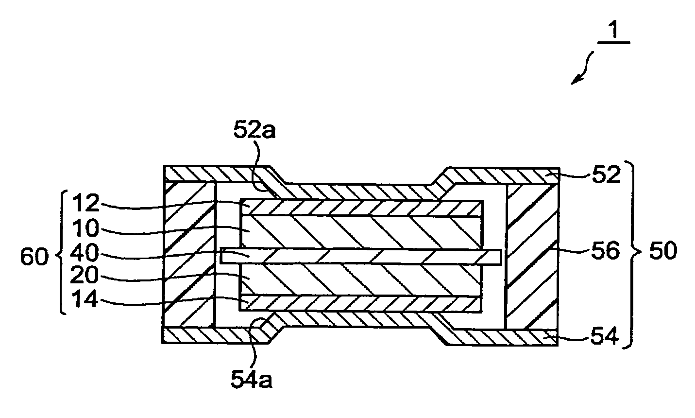
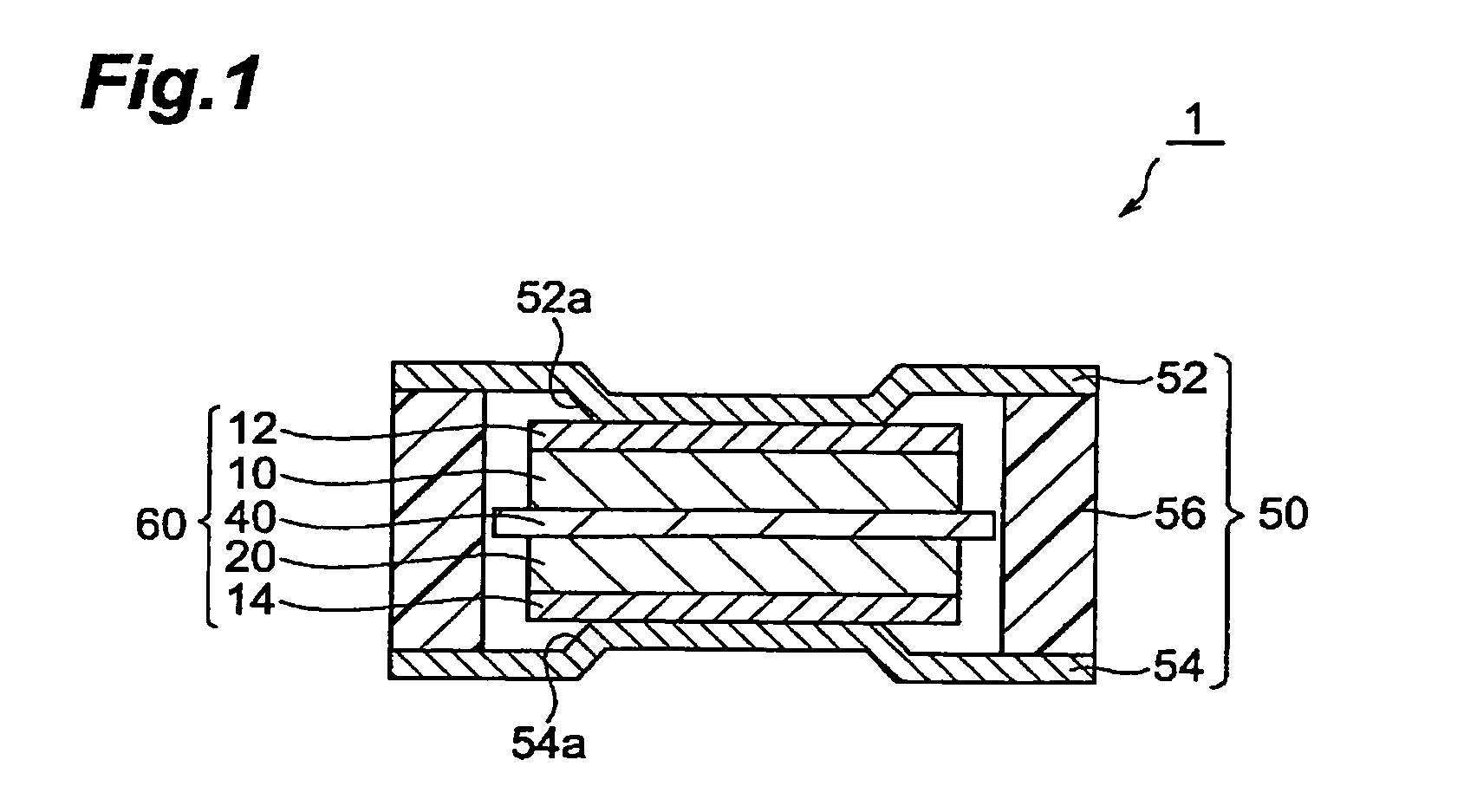
[0094]In the following procedure, an electric double layer capacitor having the same configuration as with the electric double layer capacitor 1 shown in FIG. 1 was made.

[0095](1) Making of Matrix

[0096]The anode (first electrode) and cathode (second electrode) were made by the following procedure. First, the activated carbon material (activated carbon), a thermoplastic resin (fluorine rubber) to become a binder, and a conductive auxiliary agent (carbon black) were compounded such that their mass ratios became carbon material / conductive auxiliary agent / binder=8:1:1, and the resulting mixture was put into MIBK (methylisobutylketone), which was a solvent, and mixed therewith, so as to prepare a coating liquid for forming an electrode (hereinafter referred to as “coating liquid L1”).

[0097]Subsequently, this coating liquid L1 was uniformly applied to one surface of a collector (having a thickness of 20 μm) made of an aluminum foil. Thereafter, MIBK was eliminated from the coating film by...


PUM

PropertyMeasurementUnit
sizeaaaaaaaaaa
sizeaaaaaaaaaa
temperatureaaaaaaaaaa

Abstract

An electrochemical device comprises a matrix 60 including an anode 10 and a cathode 20, an electrolyte, and a shell 50 for accommodating the matrix 60 and electrolyte in a closed state. The shell 50 includes an upper lid 52, a lower lid 54, and a gasket 56. At least one of the upper lid 52 and lower lid 54 is formed with a projection protruding toward the matrix 60 so that the upper lid 52 and the anode 10 electrically come into contact with each other and that the lower lid 54 and the cathode 20 electrically come into contact with each other.

Description

BACKGROUND OF THE INVENTION[0001]1. Field of the Invention[0002]The present invention relates to an electrochemical device; and, more specifically, to an electrochemical device encompassing electrochemical capacitors such as electric double layer capacitors and batteries such as lithium ion secondary batteries.[0003]2. Related Background of the Invention[0004]Electrochemical capacitors such as electric double layer capacitors and batteries such as lithium ion secondary batteries have been expected to become power supplies or backup power supplies for portable devices (small-size electronic devices) and the like, and auxiliary power supplies for electric or hybrid cars, for example, since they are electrochemical devices which can easily reduce their size (thickness) and weight.[0005]Among such electrochemical devices, cells having a form referred to as coin type have been known in general as those of thin type. However, such a coin type cell has a structure in which end parts of upp...

Claims


Application Information

Patent Timeline
Patent Type & Authority Patents(United States)
IPC IPC(8): H01M2/04H01G9/10H01M2/08H01M4/64H01G9/00H01G9/08H01G11/00H01G11/22H01G11/24H01G11/38H01G11/42H01G11/66H01G11/78H01G11/80H01G11/84H01G11/86H01M10/04H01M50/103H01M50/119H01M50/131H01M50/159H01M50/531
CPCH01G9/10H01M2/0202H01M2/027H01M2/0275H01M2/0404H01M2/0465H01M2/0486H01M2/26H01M10/0427H01M10/0585H01G9/155Y02T10/7022H01M2/0222H01M10/0525Y02E60/13Y02T10/7011Y02T10/70Y02E60/10H01M50/109H01M50/545H01M50/153H01M50/531Y02P70/50H01G11/80H01M50/159H01M50/103H01M50/131H01M50/119H01G11/78H01G11/74
Inventor TAKAHASHI, TETSUYAOHTSUKA, MASAYUKIMIYABARA, KUNIOTSUCHIDA, SABUROUHARANO, MITSUYOSHI
Owner TDK CORPARATION
Why Eureka
Try Eureka