Electrical connector

a technology of electrical connectors and connectors, applied in the direction of coupling contact members, coupling device connections, securing/insulating coupling contact members, etc., can solve the problems of poor yield, irregular bending, and insufficient operation speed to meet user's requirements, etc., to improve improve the effect of the first terminal, and improve the effect of the structure of the first terminal

Inactive Publication Date: 2015-10-13
ADVANCED CONNECTEK INC
View PDF2 Cites 4 Cited by
  • Summary
  • Abstract
  • Description
  • Claims
  • Application Information

AI Technical Summary

Benefits of technology

[0011]In summary, the electrical connector according to the present invention improves the structure of the first terminal, by forming a stair-like structure with the second connecting part, the third connecting part, the first bending part, the second bending part and the third bending part of the exposed portion of the first terminal, thereby solving the foregoing problems that too much of the first terminal is exposed from the base without any abutment piece, which subsequently caused irregular bending and poor evenness of the surface of the first terminal.
[0012]Besides, a dividing board is disposed between two adjacent ones of the connecting parts, allowing the first terminals to have better high frequency characteristics, preventing the first terminal to be too close causing short circuit as a result of arc breakdown during voltage test.

Problems solved by technology

However, the function of mSATA in practice does not produce satisfactory results as expected.
Besides, the operational speed is no longer sufficient to meet user's requirement.
Nevertheless, according to the drawings of the previously mentioned patent, the part of first terminal which is exposed from the insulative body of the NGFF connector disclosed by the previously mentioned patent is long and each of the first terminals is not securely fastened with any petitioners, such that first terminals can easily become deformed, causing failure to be successfully bonded onto the circuit board, resulting in poor yield.

Method used


Image

  • Electrical connector
  • Electrical connector
  • Electrical connector

Examples


Embodiment Construction

[0023]The present invention is described in the following with specific embodiments, so that one skilled in the pertinent art can easily understand other advantages and effects of the present invention from the disclosure of the present invention.

[0024]It is to be understood that the scope of the present invention is not limited to the disclosed embodiments. On the contrary, it is intended to cover various modifications and similar arrangements. The scope of the claims, therefore, should be accorded the broadest interpretation so as to encompass all such modifications and similar arrangements. In addition, words such as “on”, “top” and “a” are used to explain the preferred embodiment of the present invention only and should not limit the scope of the present invention.

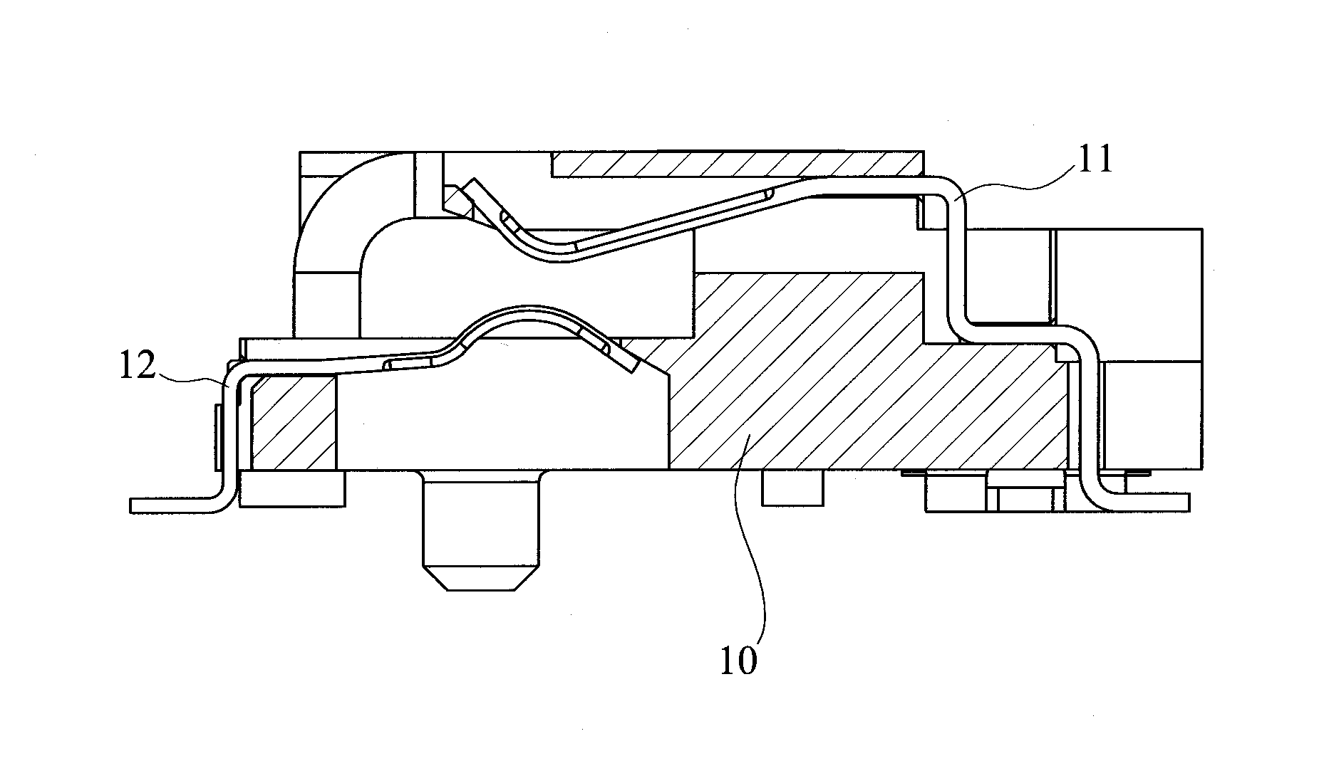
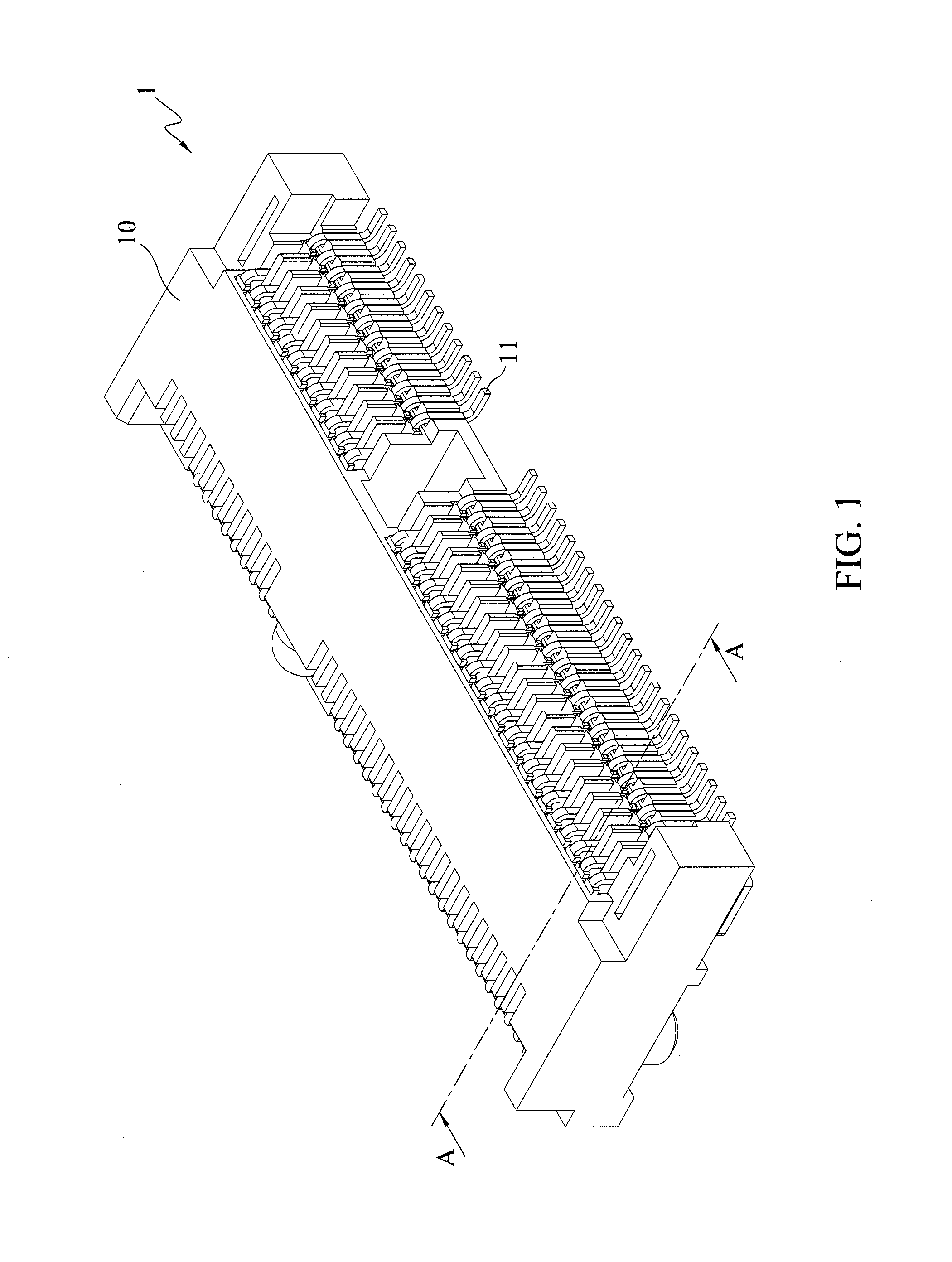
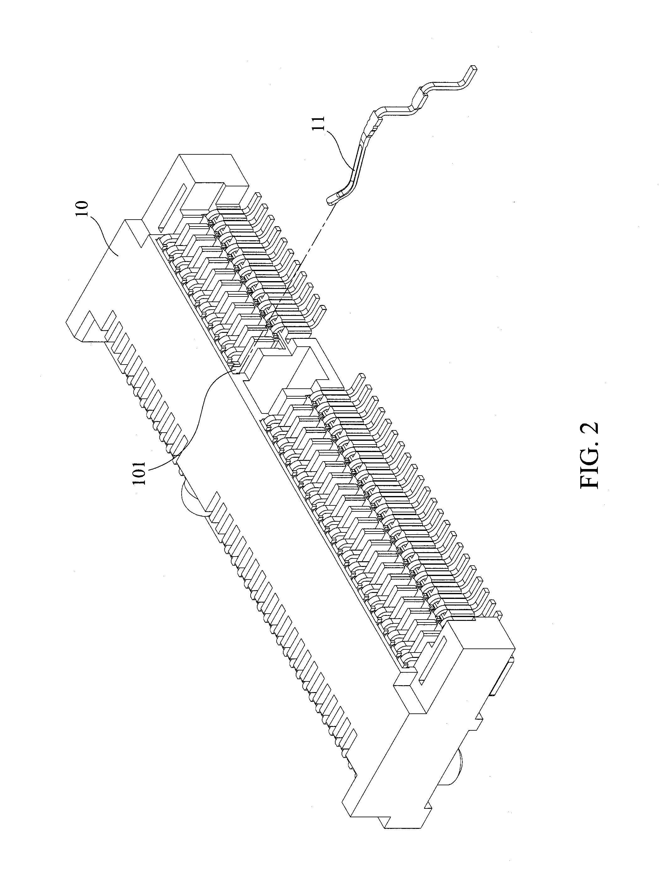
[0025]FIGS. 1 to 3 show an electrical connector 1 according to the present invention. FIG. 1 is the 3 D view of the electrical connector 1 according to the present invention. FIG. 2 is the detached schematic view showi...


PUM


Abstract

An electrical connector to be connected with an Next Generation Form Factor (NGFF) interface is disclosed, including a base, a plurality of first terminals, and a plurality of second terminals. A plurality of first terminal slots parallel disposed on one side of the base for the first terminals to be plugged thereinto. A plurality of second terminal slots parallel disposed on the other side of the base for the second terminals to be plugged thereinto. The first terminal has a stair-like structure having a first plugging part, a first connecting part, a second connecting, a third connecting part, and a first bonding part. The present invention discloses an improved first terminal structure from having only one abutment piece to having a stair-like structure with a plurality of connecting parts.

Description

BACKGROUND OF THE INVENTION[0001]1. Field of the Invention[0002]The present invention relates to electrical connectors, and, more particularly, to an electrical connector used to connect with a Next Generation Form Factor (NGFF) interface.[0003]2. Description of Related Art[0004]As the technology for developing electronic products is rapidly growing, many different types of electronic devices have been developed including personal computers, smart phones or tablets. The goal for today's electronic device is centered towards miniaturization, high operational speed, and high functionality.[0005]In recent years, the industry focuses heavily on improving Notebook and Ultrabook by using mSATA as an interface to connect with SSD. However, the function of mSATA in practice does not produce satisfactory results as expected. The advantages of using mSATA are few compared to its price. Besides, the operational speed is no longer sufficient to meet user's requirement.[0006]In view of this, rel...

Claims


Application Information

Patent Timeline
Patent Type & Authority Patents(United States)
IPC IPC(8): H01R12/71H01R13/41H01R13/24H01R12/72
CPCH01R12/716H01R13/41H01R13/2442H01R12/721
Inventor TSAI, YU-LUNHOU, PIN-YUAN
Owner ADVANCED CONNECTEK INC
Why Eureka
Try Eureka