Sprinkler anchor

a technology of sprinkler head and anchor, which is applied in the direction of stand/trestle, travel articles, kitchen equipment, etc., can solve the problems of sprinkler head removal, arduous and troublesome task of setting and resetting sprinkler head, and few residences or businesses can afford a system of this typ

Active Publication Date: 2008-12-30
MAYORGA PETE
View PDF20 Cites 18 Cited by
  • Summary
  • Abstract
  • Description
  • Claims
  • Application Information

AI Technical Summary

Benefits of technology

[0010]The sprinkler anchor may further include at least two linear channels, one or more hollow flanges, a plurality of anchoring studs, and a cap. The linear channels are disposed through the upper support plate and intersect at the center aperture, forming a continuous aperture therewith. The one or more hollow flanges depend from the bottom side of the upper support plate adjacent to one of linear channels and are configured to receive the winged sides that may be part of the ground spike of the sprinkler head. The plurality of anchoring studs depend from the periphery of the bottom side of the upper support plate for helping to further support the sprinkler anchor in the ground. The cap is designed to cover the sprinkler anchor when not in use and has a top side and a bottom side with a handle member extending from the top side and a plug member depending from the bottom side. The plug member is configured to fit tightly within the linear channels disposed along the top side of the upper support plate.

Problems solved by technology

Few residences or businesses can afford a system of this type.
In this operation, the setting and resetting of spiked sprinkler heads is an arduous and troublesome task.
But the spiked sprinkler head must be removed as they present a hazard to children playing on the lawn and an accident waiting to happen when mowing the lawn.
These devices do avoid the need for pulling up spiked sprinklers but they are subject to tipping over under use and they can are expensive.
Clearly, the need to remove spiked sprinklers each time the lawn is to be mowed is a problem, as is the stability of the four-legged platform sprinkler.

Method used


Image

  • Sprinkler anchor
  • Sprinkler anchor
  • Sprinkler anchor

Examples


Embodiment Construction

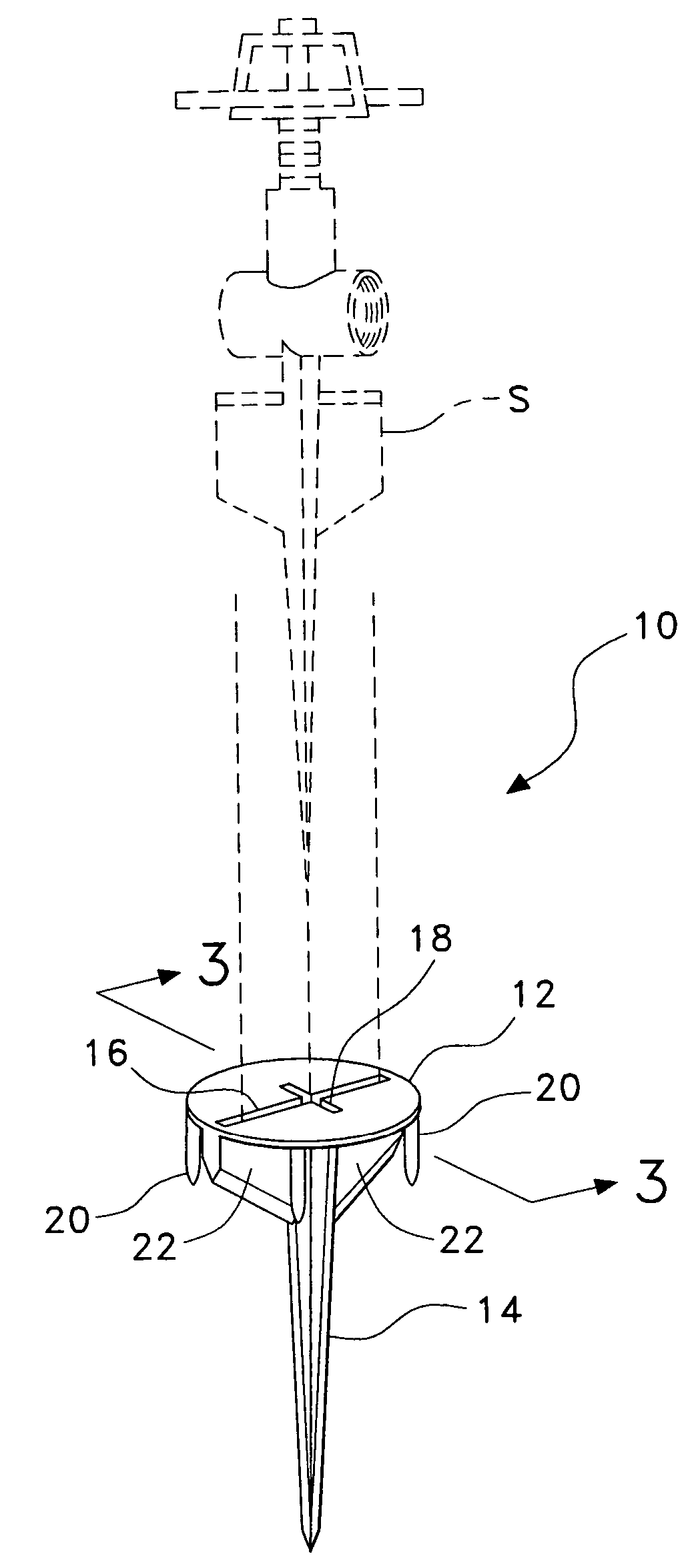
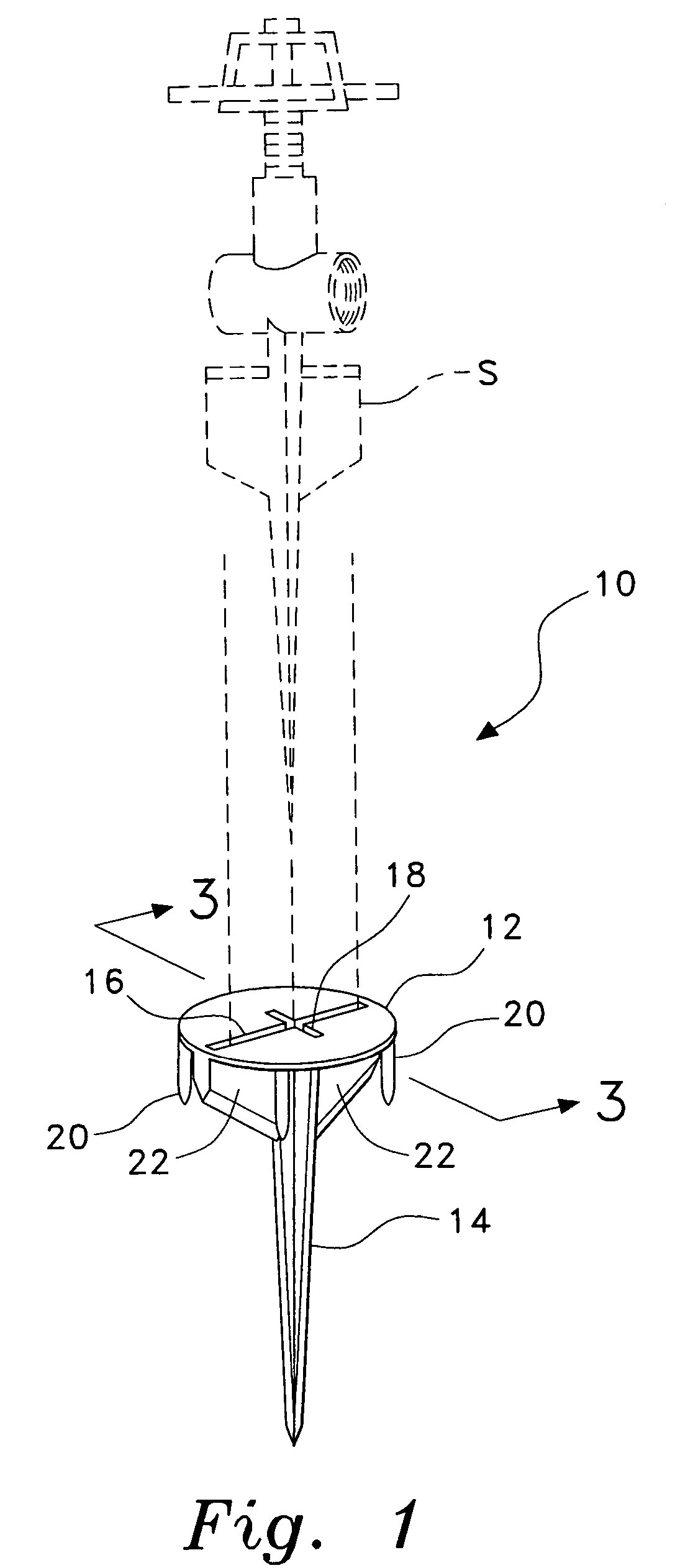
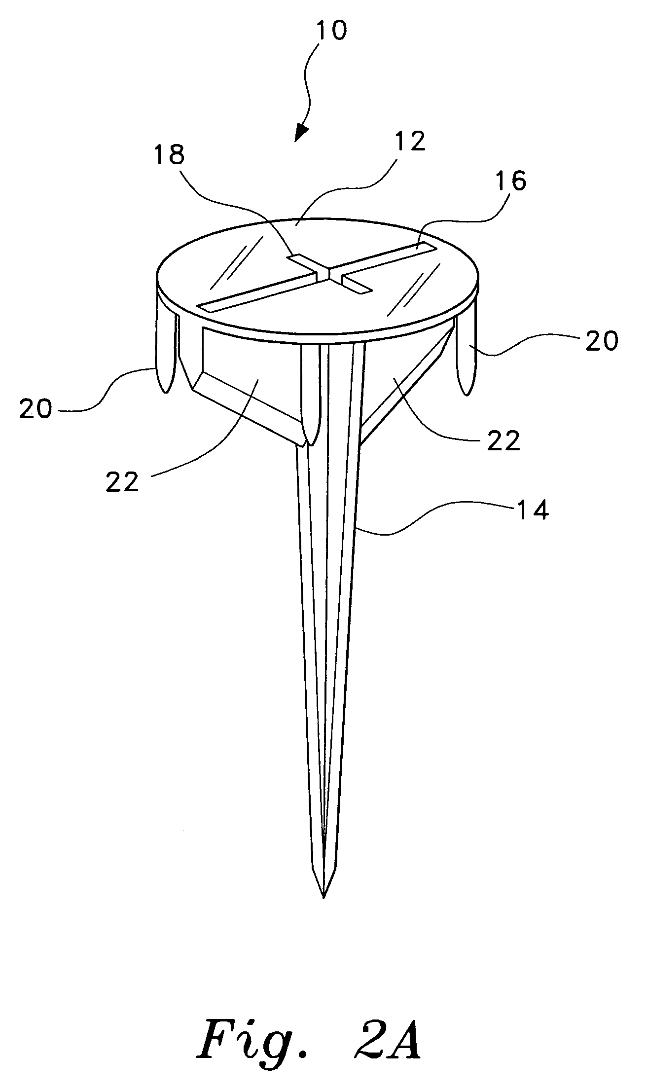
[0019]The present invention is a sprinkler anchor, a preferred embodiment of which is designated generally as 10 in the drawings, for supporting and anchoring a traditional sprinkler head having a ground spike.

[0020]Referring to FIGS. 1, 2A, 2B, 2C, and 3, anchor 10 is shown including an upper support plate 12, a hollow, tapered stake 14, linear channels 16 and 18, a plurality of hollow flanges 22, a plurality of anchoring studs 20, and a cap 24. Upper support plate 12 has a top side and a bottom side and a center aperture therethrough. Hollow, tapered stake 14 is depends from the bottom side of upper support plate 12 proximal the center aperture therethrough, and forms a continuous aperture with the center aperture for receiving the ground spike of sprinkler head S. Hollow, tapered stake 14 terminates in a point and is, itself, designed to engage the earth, in the same manner as the ground spike of sprinkler head S would. In a preferred embodiment, upper support plate 12 is circula...


PUM


Abstract

The sprinkler anchor is designed to anchor and support a convention sprinkler head having a ground spike and includes an upper support plate and a hollow, tapered stake. The upper support plate and the stake form a continuous aperture for receiving the ground spike of the sprinkler head, with the stake being configured for engaging the ground. The sprinkler anchor may further include at least two linear channels, one or more hollow flanges, a plurality of anchoring studs, and a cap. The linear channels, hollow flanges, and anchoring studs are provided to further help the sprinkler anchor in receiving the sprinkler head and securing it into the ground. The cap is designed to cover the sprinkler anchor when not in use in order to prevent debris from entering.

Description

CROSS-REFERENCE TO RELATED APPLICATION[0001]This application claims the benefit of U.S. Provisional Patent Application Ser. No. 60 / 690,525, filed Jun. 15, 2005.BACKGROUND OF THE INVENTION[0002]1. Field of the Invention[0003]The present invention relates to anchoring devices for lawn care systems, and more specifically to an anchoring device for supporting a manual sprinkler head having a ground spike.[0004]2. Description of the Related Art[0005]The watering of lawns and flower beds is a required activity in city and suburbs throughout the country. The task can be automated by installing subsurface water piping to feed sprinklers that rise above ground and rotate when the water pressure is turned on and then settle to ground level when the water flow stops. The system can be further automated to start up at a pre-selected time and run for a predetermined amount of time. Few residences or businesses can afford a system of this type. By far, the more common method to water lawns relies...

Claims


Application Information

Patent Timeline
Patent Type & Authority Patents(United States)
IPC IPC(8): B05B15/06A62C31/22F16M13/00
CPCB05B15/065B05B15/65
Inventor MAYORGA, PETE
Owner MAYORGA PETE
Why Eureka
Try Eureka