Rotor magnet placement in interior permanent magnet machines

a permanent magnet machine and magnet technology, applied in the direction of dynamo-electric machines, magnetic circuit rotating parts, magnetic circuit shape/form/construction, etc., can solve the problems of rotor loss and magnet heating, complicated rotor manufacturing, and magnets that are vulnerable to demagnetization, so as to reduce the variation of rotor flux

Active Publication Date: 2009-01-06
GM GLOBAL TECH OPERATIONS LLC
View PDF35 Cites 38 Cited by
  • Summary
  • Abstract
  • Description
  • Claims
  • Application Information

AI Technical Summary

Benefits of technology

[0006]In another embodiment, a machine includes a stator and a rotor separated from the stator by an air gap and having a plurality of slots and a plurality of permanent magnets located in at least several of the slots to form a rotor pole. Each magnet is recessed within the rotor so as to minimize rotor flux variation inside the magnet during rotation of the rotor relative to the stator.

Problems solved by technology

Flux variation causes eddy currents to be induced in the rotor and the magnets, especially near the surface of the rotor, and can result in rotor losses and magnet heating.
For high-frequency operation, for example, in many automotive variable speed drive applications, eddy current losses can make the magnet vulnerable to demagnetization.
This process, however, can make the rotor manufacturing more complicated where a large number of magnet segments are required to be inserted into the rotor.

Method used


Image

  • Rotor magnet placement in interior permanent magnet machines
  • Rotor magnet placement in interior permanent magnet machines
  • Rotor magnet placement in interior permanent magnet machines

Examples


first embodiment

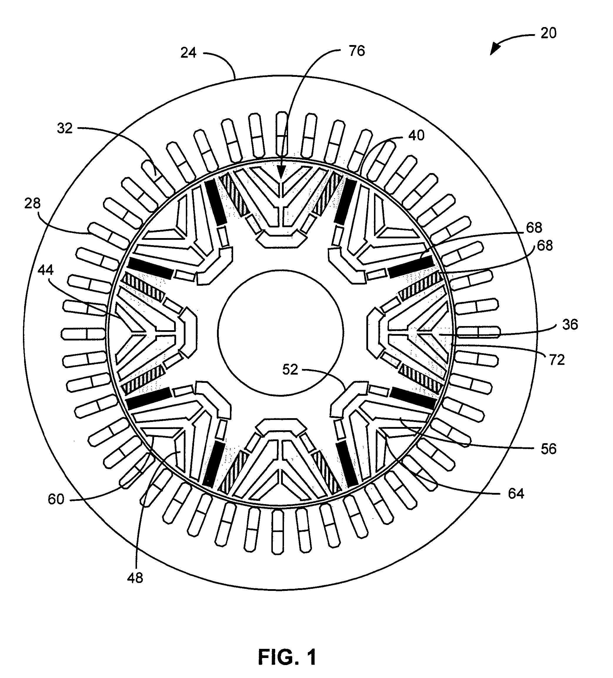
[0017]A cross-sectional view of a multi-barrier synchronous IPM machine is indicated generally in FIG. 1 by reference number 20. The machine 20 includes a stator 24 having a plurality of slots 28 through which multiphase windings 32 are wound. In the embodiment shown in FIG. 1, the stator 24 has forty-eight slots 28. A rotor 36 is separated from the stator 24 by an air gap 40. A plurality of slots 44 in the rotor 36 form a plurality of barriers 48, for example, inner barriers 52, middle barriers 56 and outer barriers 60. The slots 44 in a barrier 48 may be separated by bridges 64.

[0018]A plurality of sintered permanent magnets 68 are located in slots 44 of the inner barriers 52 near an outer surface 72 of the rotor 36. The rotor 36 includes a plurality of magnetic poles, one of which is indicated generally by reference number 76. Each pole 76 is formed at least in part by the magnets 68 in the slots 44. In the embodiment shown in FIG. 1, the rotor 36 has eight poles 76.

[0019]The afo...

second embodiment

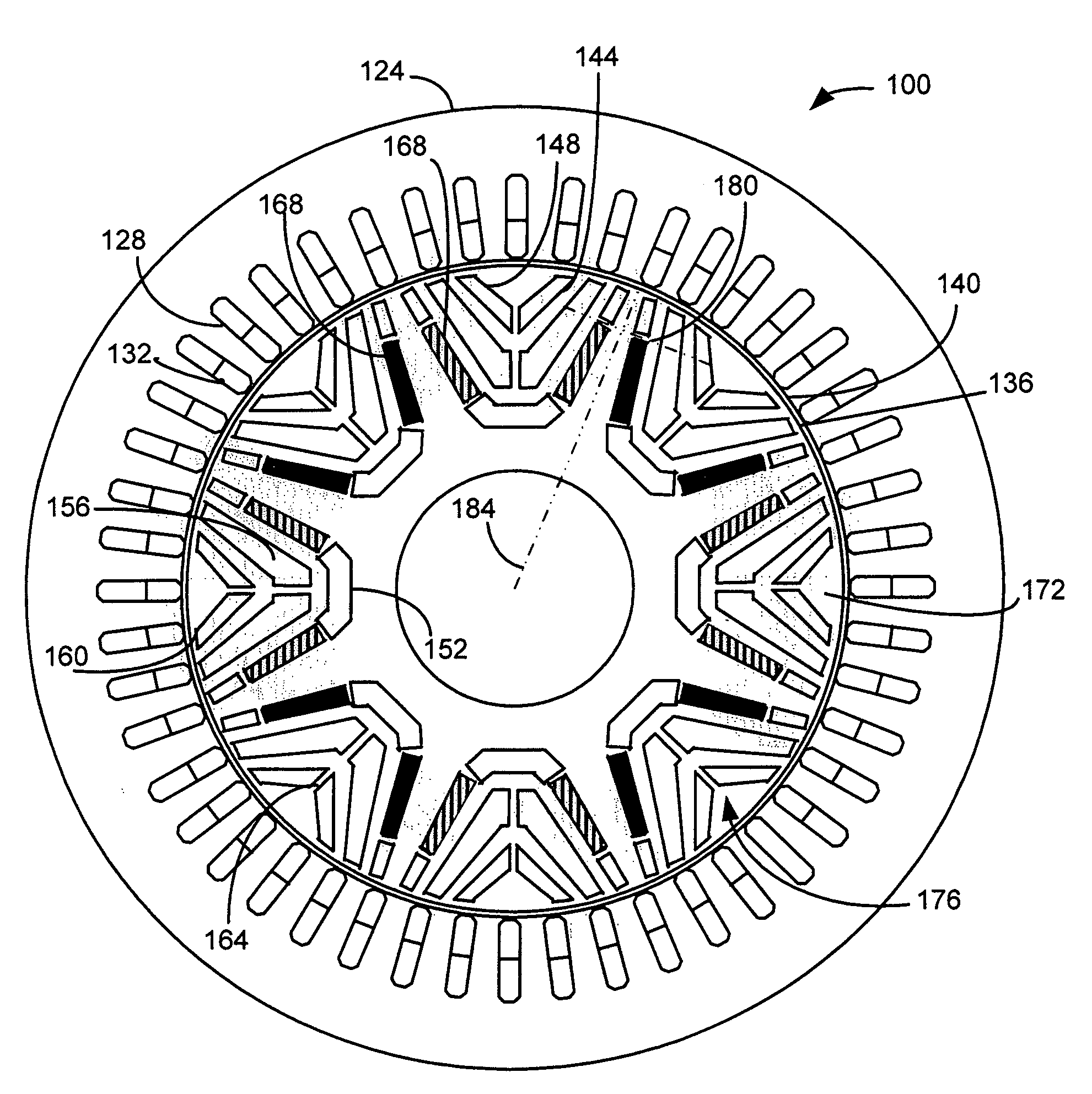
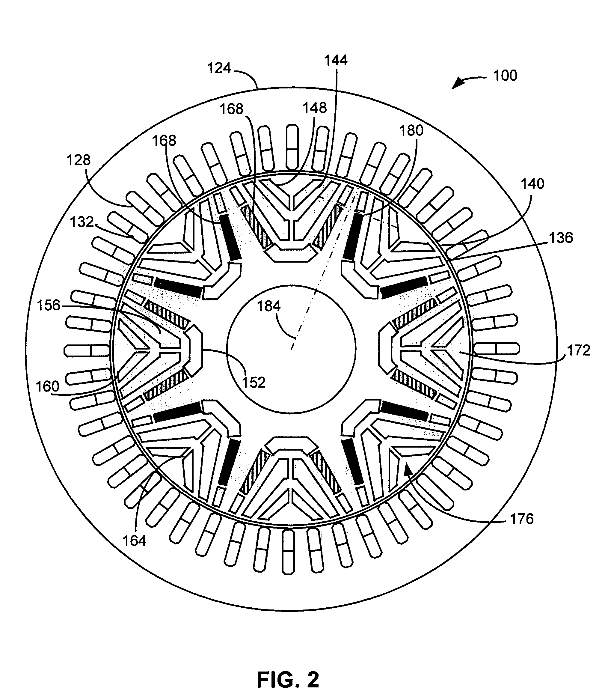
[0021]A cross-sectional view of a multi-barrier IPM machine is indicated generally in FIG. 2 by reference number 100. The machine 100 includes a stator 124 having a plurality of slots 128 through which multiphase windings 132 are wound. In the embodiment shown in FIG. 2, the stator 124 has forty-eight slots 128. A rotor 136 is separated from the stator 124 by an air gap 140. A plurality of slots 144 in the rotor 136 form a plurality of barriers 148, for example, inner barriers 152, middle barriers 156 and outer barriers 160. The slots 144 in each barrier 148 may be separated by bridges 164.

[0022]A plurality of sintered permanent magnets 168 are located in slots 144 of the inner barriers 152. The rotor 136 includes a plurality of magnetic poles, one of which is indicated generally by reference number 172. Each pole 172 is formed at least in part by the magnets 168 in the slots 144. In the embodiment shown in FIG. 2, the rotor 136 has eight poles 172.

[0023]The magnets 168 are recesse...


PUM


Abstract

A machine includes a stator and a rotor having a plurality of poles. Each pole is formed at least in part by a plurality of permanent magnets recessed within the rotor at a predetermined distance from an outer surface of the rotor. The distance is predetermined to minimize rotor flux variation near the outer surface during rotation of the rotor relative to the stator. Eddy current losses are thereby reduced.

Description

FIELD OF THE INVENTION[0001]The present invention relates generally to interior permanent magnet machines and, more particularly to placement of magnets in a rotor of an interior permanent magnet machine.BACKGROUND OF THE INVENTION[0002]Interior permanent magnet (IPM) machines have a number of operating characteristics that make them attractive for use in vehicle propulsion applications. Compared, for example, to AC induction and DC motors, IPM motors can provide high efficiency, high torque and high power densities. IPM machines also have a long constant power operating range. An IPM machine typically includes a stator with multiphase windings. A rotor having interior permanent magnets is separated from the stator by an air gap. A magnetic field, produced by the flow of current through the stator windings, interacts with a magnetic field produced by the rotor magnets, thereby causing the rotor to rotate.[0003]Permanent magnets have low permeability and therefore exhibit high reluct...

Claims


Application Information

Patent Timeline
Patent Type & Authority Patents(United States)
IPC IPC(8): H02K21/12H02K1/27
CPCH02K1/2766
Inventor RAHMAN, KHWAJA M.NAGASHIMA, JAMES M.
Owner GM GLOBAL TECH OPERATIONS LLC
Why Eureka
Try Eureka