Electromagnetic relay

a technology of electromagnetic relays and relays, applied in the direction of relays, electromagnetic relay details, contacts, etc., can solve the problem of a large circuit footprint when installed on an external circuit board

Inactive Publication Date: 2009-01-13
GOOD SKY ELECTRIC
View PDF20 Cites 43 Cited by
  • Summary
  • Abstract
  • Description
  • Claims
  • Application Information

AI Technical Summary

Problems solved by technology

As a result, the conventional electromagnetic relay 100 has a relatively long length in the direction (L), thereby resulting in a relatively large circuit footprint when installed on an external circuit board.

Method used


Image

  • Electromagnetic relay
  • Electromagnetic relay
  • Electromagnetic relay

Examples


Embodiment Construction

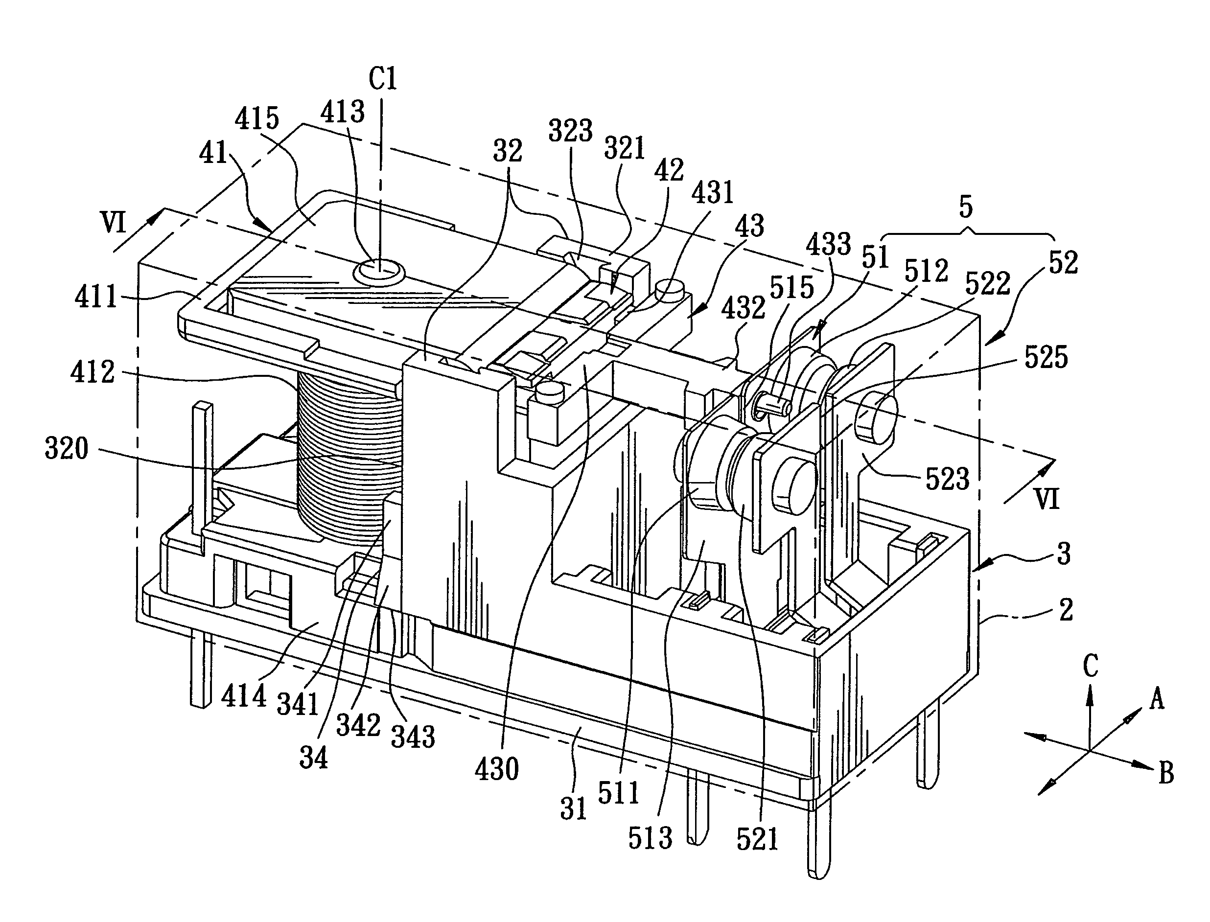
[0029]Referring to FIGS. 4 to 6, the preferred embodiment of an electromagnetic relay according to the present invention is shown to include a housing 1, a conductive plate unit 5, and a magnetic pushing device 4.

[0030]The housing 1 has a base seat 3, and a cover body 2 covering the base seat 3 and cooperating with the base seat 3 to define an inner accommodating space 21 (see FIG. 6) therebetween. The base seat 3 includes a bottom wall 31, and opposite mounting wall 32 extending uprightly from the bottom wall 31, spaced apart from each other in a first direction (A) and cooperating with the bottom wall 31 so as to define a receiving groove 33 (see FIG. 5) thereamong. In this embodiment, each mounting wall 32 has a top end 321, a lateral side 320, an inner surface 322 formed with a guiding groove 323 that extends downwardly from the top end 321, and an engaging block 34 formed integrally on the lateral side 320. The guiding groove 323 in each mounting wall 32 has an upwardly divergi...


PUM


Abstract

An electromagnetic relay includes an electromagnetic unit operable so as to generate a magnetic field perpendicular to a bottom wall of a housing when excited such that an actuating plate pivots from a releasing position to a pushing position, where a magnetically-attractable end portion of the actuating plate is attracted by the electromagnetic unit and where an actuating end portion of the actuating plate moves toward a first conductive plate, thereby driving a pushing block to move a resilient end portion of the first conductive plate toward a second conductive plate. Hence, first and second contacts on the first conductive plate contact electrically and respectively third and fourth contacts on the second conductive plate.

Description

BACKGROUND OF THE INVENTION[0001]1. Field of the Invention[0002]The invention relates to an electromagnetic device, more particularly to an electromagnetic relay.[0003]2. Description of the Related Art[0004]FIGS. 1 and 2 illustrate a conventional electromagnetic relay 100 that includes: a base seat 11 having a bottom wall 110, an electromagnetic 12 mounted in the base seat 11 and having two ends opposite to each other in a direction (L) that is parallel to the bottom wall 110, and a set of coil strands wound around an iron core (not shown) about a center axis (X) of the iron core parallel to the direction (L); a magnetically attractable actuating plate 13 mounted movably in the base seat 11 and disposed adjacent to one of the ends of the electromagnetic 12; a resilient first conductive plate 15 mounted in the base seat 11 and disposed adjacent to the other one of the ends of the electromagnetic 12; a second conductive plate 14 mounted in the base seat 11 and distal from the electrom...

Claims


Application Information

Patent Timeline
Patent Type & Authority Patents(United States)
IPC IPC(8): H01H51/22H01H67/02
CPCH01H50/043H01H50/026H01H50/26H01H50/642
Inventor WU, TE-KANG
Owner GOOD SKY ELECTRIC
Why Eureka
Try Eureka