
Orthodontic force measurement system

a force measurement and orthodontic technology, applied in the field of orthodontics, can solve the problems of inaccuracy of the system that exists for obtaining such measurements, difficult to replicate, and take a long time and effort to obtain a force measuremen

Active Publication Date: 2009-01-27
ALIGN TECH
View PDF4 Cites 33 Cited by
  • Summary
  • Abstract
  • Description
  • Claims
  • Application Information

AI Technical Summary

Problems solved by technology

Currently, the systems that exist for obtaining such measurements suffer from issues of inaccuracy and their ability to look at multiple teeth and their movements relative to each other.
Thus, it takes much time and effort to obtain a force measurement for multiple teeth within the jaw structure, and any result can rarely be replicated.

Method used


Image

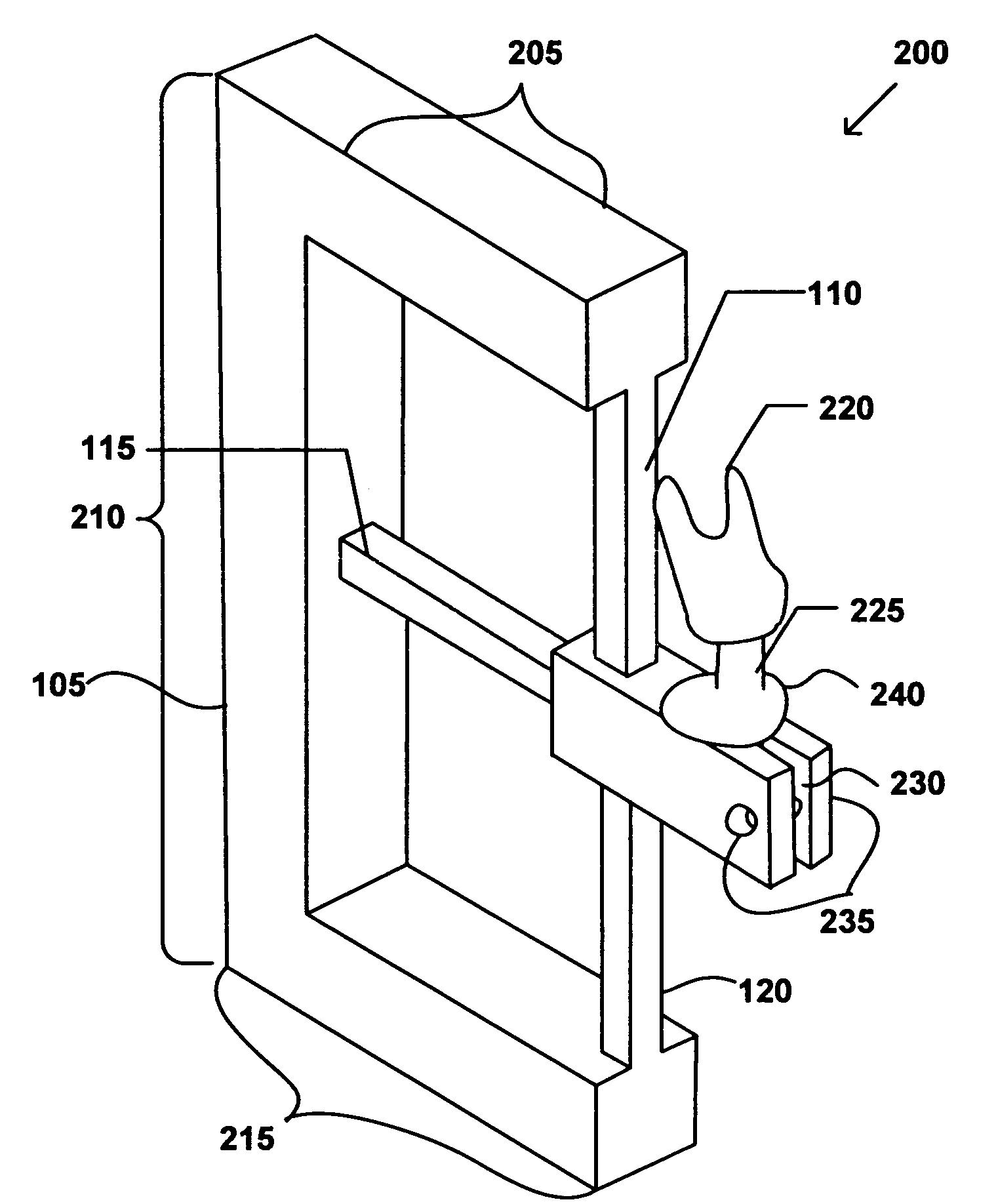
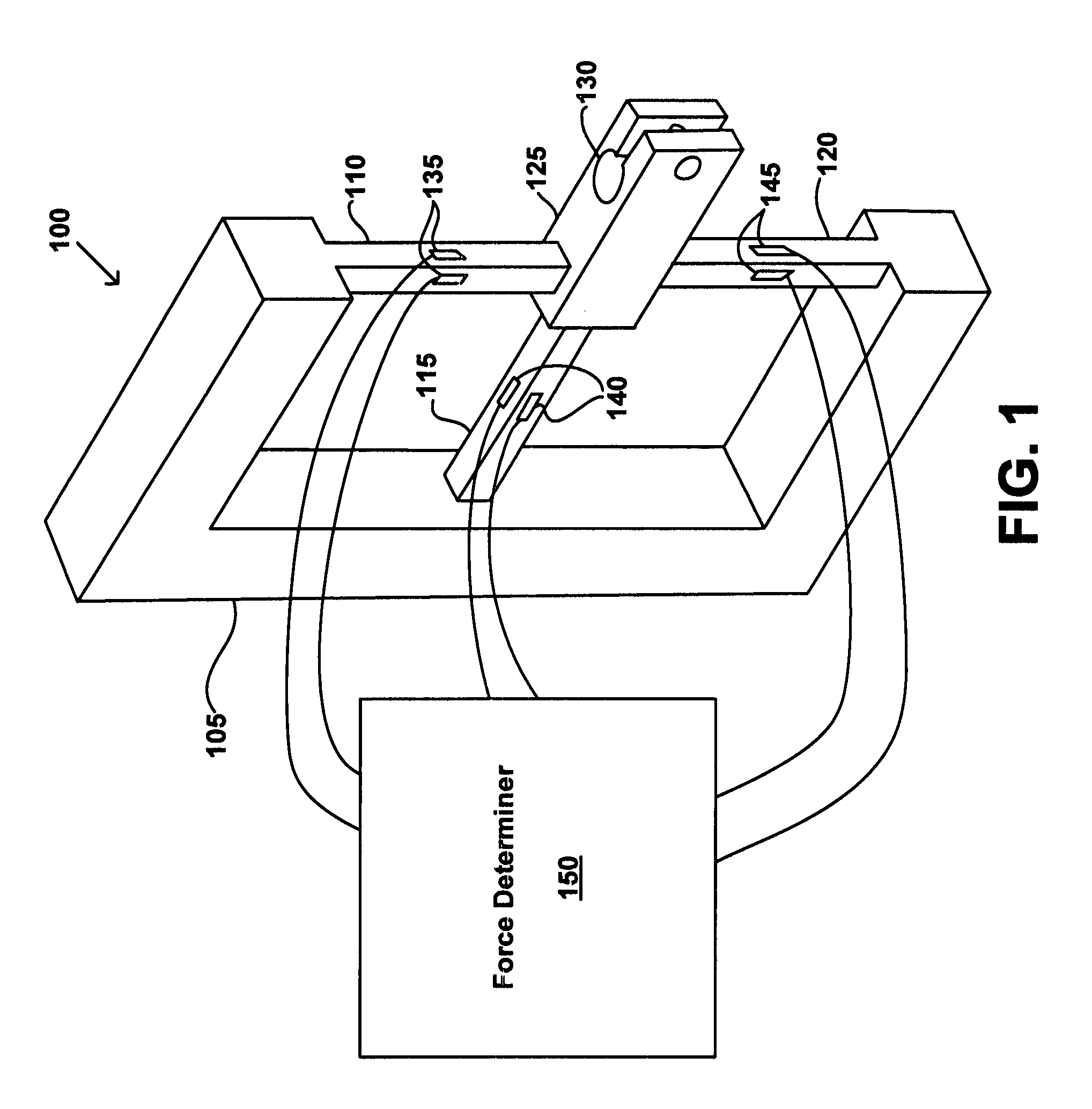
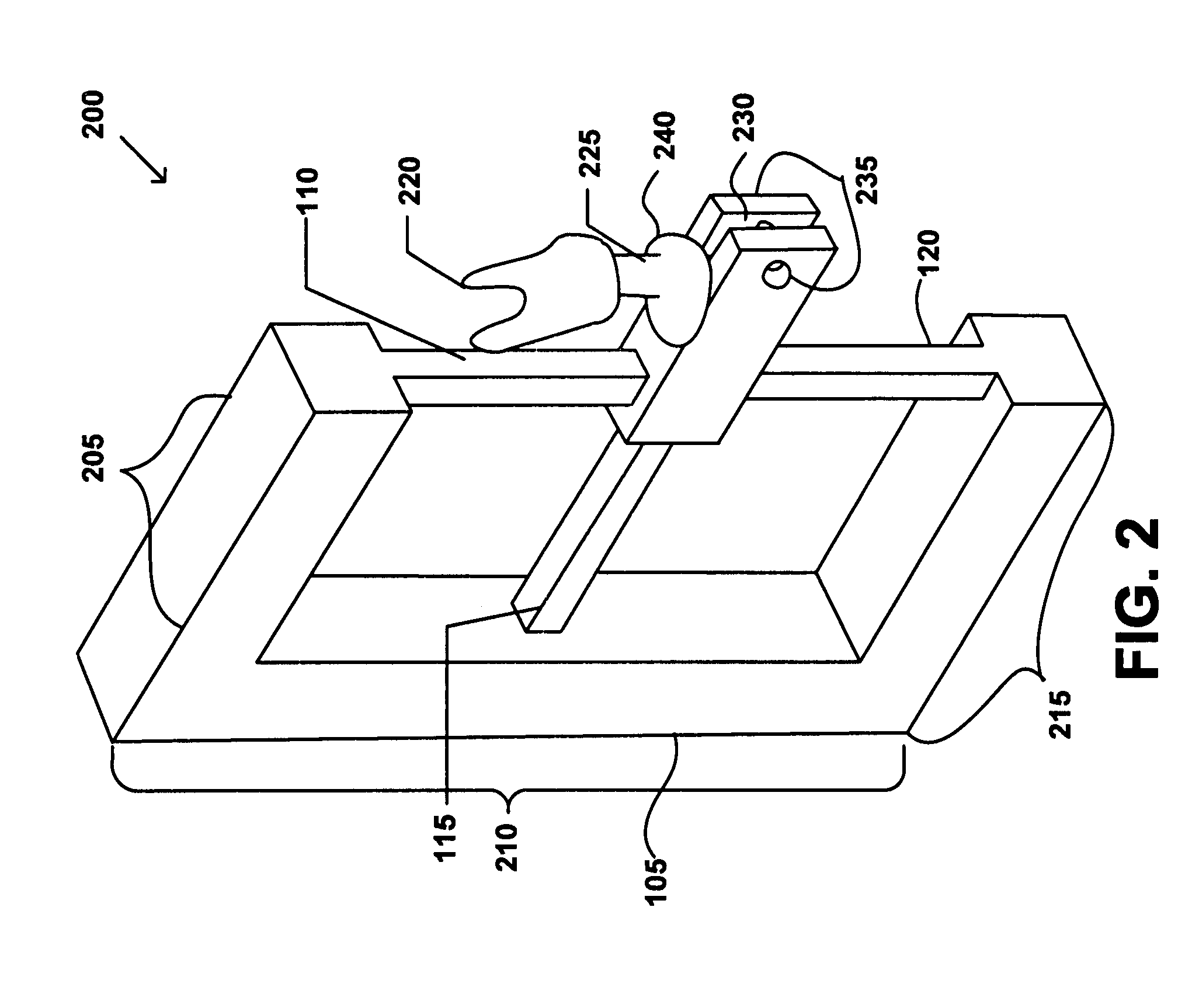
  • Orthodontic force measurement system
  • Orthodontic force measurement system
  • Orthodontic force measurement system

Examples


Embodiment Construction

[0013]Before the present force gauge tool, force measurement systems and methods are described, it is to be understood that this invention is not limited to particular tools, systems and methods specifically described, as such may, of course, vary. It is also to be understood that the terminology used herein is for the purpose of describing particular embodiments only, and is not intended to be limiting, since the scope of the present invention will be limited only by the appended claims.

[0014]Unless defined otherwise, all technical and scientific terms used herein have the same meaning as commonly understood by one of ordinary skill in the art to which this invention belongs. Although any methods and materials similar or equivalent to those described herein can be used in the practice or testing of the present invention, some potential and preferred methods and materials are now described.

[0015]It must be noted that as used herein and in the appended claims, the singular forms “a”,...


PUM


Abstract

A method for concurrently measuring a force exerted upon each of a plurality of teeth is disclosed. A dentition crown connecting rod associated with a force gauge is positioned such that a dentition crown coupled to the dentition crown connecting rod may be received within a corresponding cavity of a reference aligner. A measurement aligner is then applied to the dentition crown, wherein the dentition crown is positioned to be received within a corresponding cavity of a reference aligner. A force exerted on the dentition crown by the measurement aligner is then calculated.

Description

FIELD OF THE INVENTION[0001]The present invention relates generally to the field of orthodontics.BACKGROUND OF THE INVENTION[0002]Orthodontic treatments involve repositioning misaligned teeth and improving bite configurations for improved cosmetic appearance and dental function. Repositioning is typically accomplished by a dentist or orthodontist (hereinafter practitioner) applying gentle forces by a dental appliance (e.g., braces or positioning appliances) to a patient's teeth over an extended period of time. Due to the limited space within the oral cavity and extensive movements that some teeth must undergo, the teeth will often be moved throughout a series of intermediate patterns to properly arrange the teeth.[0003]Braces comprise a variety of appliances such as brackets, bands, archwires, ligatures, and O-rings. After the brackets are bonded to the teeth, periodic meetings with the treating practitioner are required to allow them to reactively adjust the braces. This generally ...

Claims


Application Information

Patent Timeline
IPC IPC(8): G01L1/22
CPCA61C7/00A61C19/04G01L5/161G01L5/1627
Inventor CAO, HENG
Owner ALIGN TECH
Learn More