Pipe connector and a method for production thereof

Inactive Publication Date: 2009-02-17
PARKER HANNIFLIN
View PDF17 Cites 5 Cited by
  • Summary
  • Abstract
  • Description
  • Claims
  • Application Information

AI Technical Summary

Benefits of technology

[0011]The object of the present invention is a high-pressure union, its realization and the tools required for its realization. The union is designed as a positive system with a high degree of safety, and is useful as a tube connector for metallic tubes for high and maximum pressures

Problems solved by technology

In particular, complex tube deformations cannot be realized with the known upsetting procedures.
It cannot, however, control high and maximum pressures.
This known system does not offer receiving space for a seal.
Likewise, the radial face of the connecting piece is not used or only insufficiently used in special cases so that transfer of the assembly forces onto the tube to be connected essentially takes place via inclined surfaces, resulting in the exclusive use of components of the forces applied.
It is true that this permits assembly on a block, but there is

Method used


Image

  • Pipe connector and a method for production thereof
  • Pipe connector and a method for production thereof
  • Pipe connector and a method for production thereof

Examples


Example

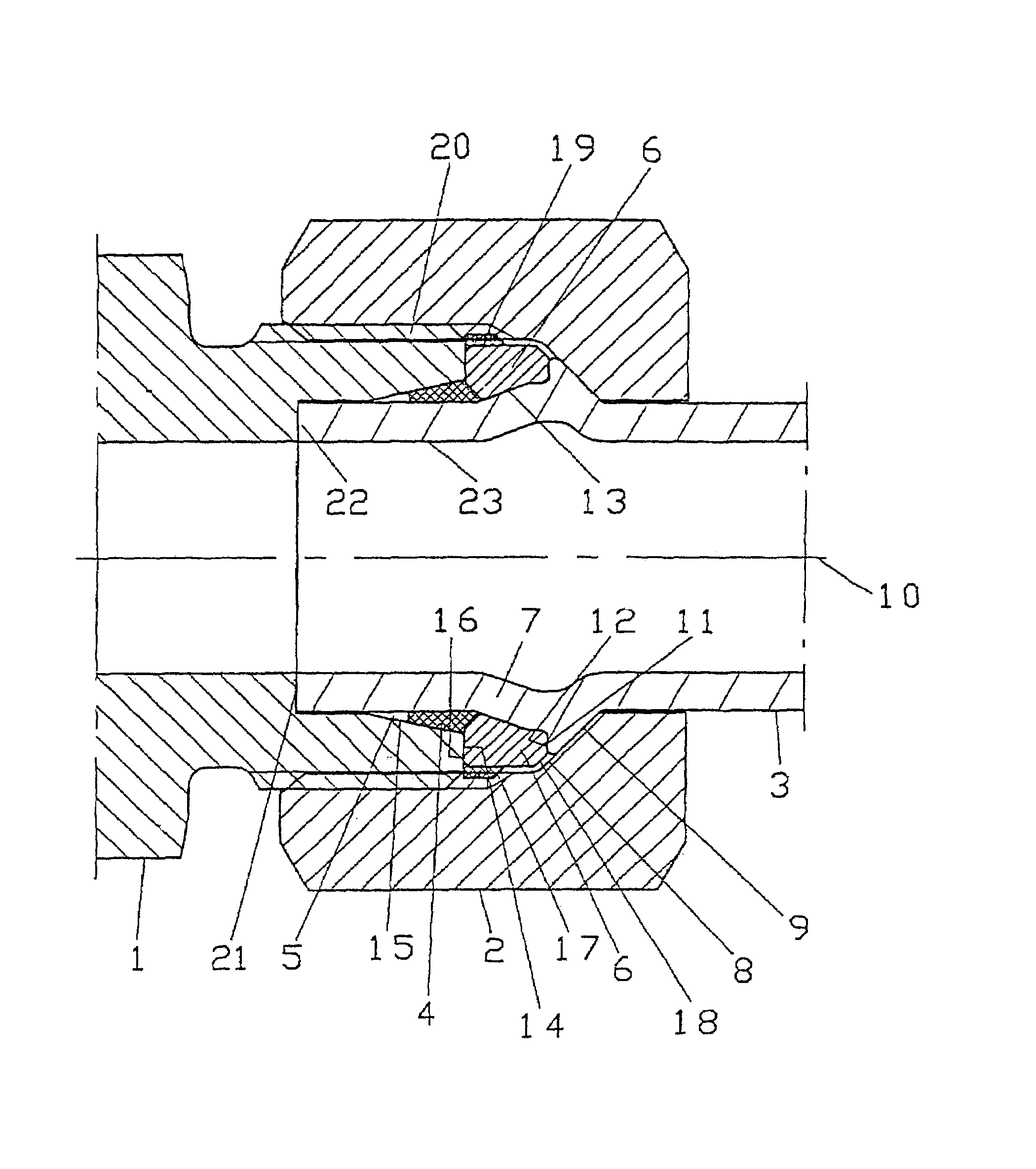
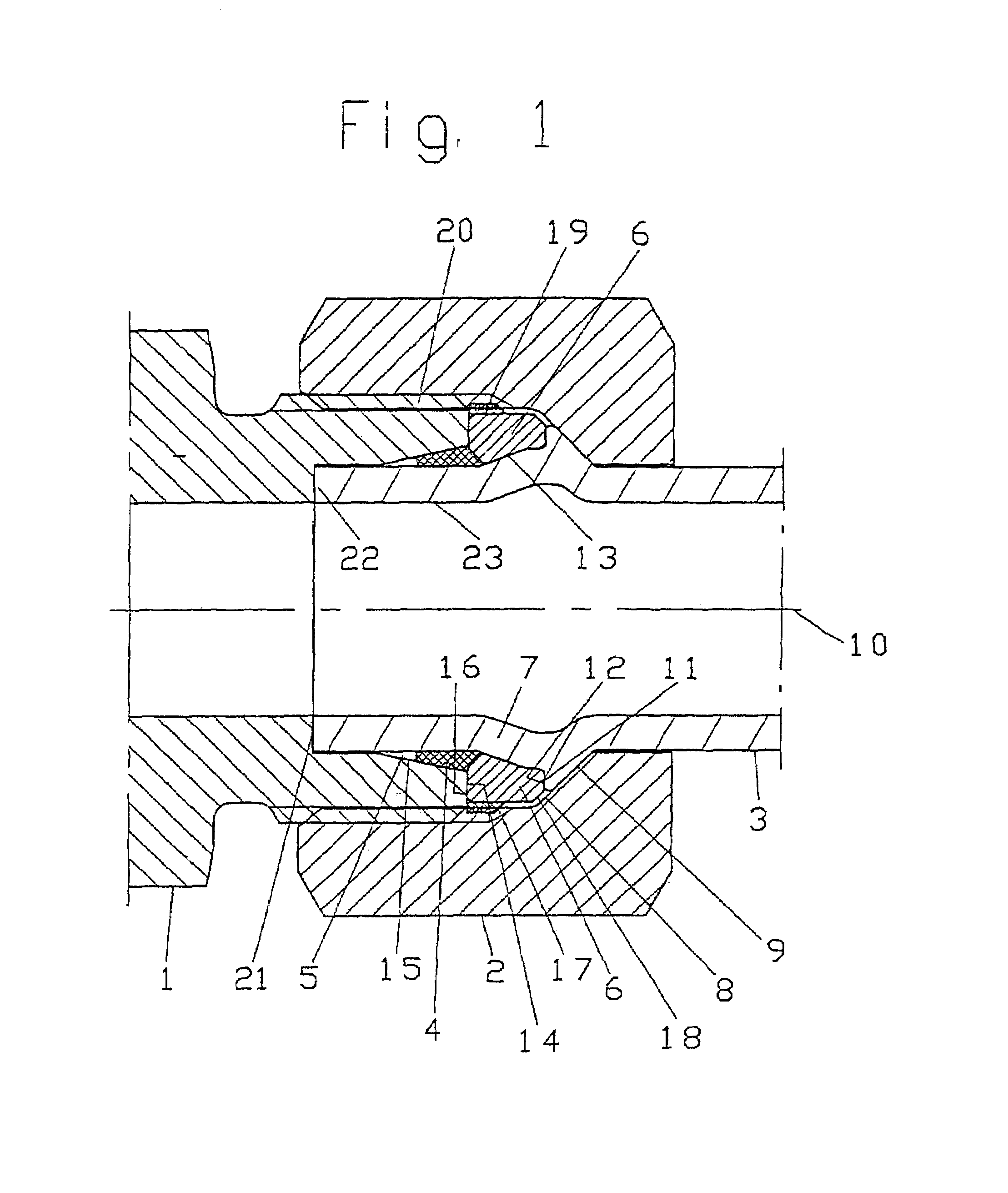
[0048]The connection system shown in FIG. 1 consists of a union member (or connecting piece) 1 with a conical opening 15 which, in a practical example, is designed as a standardized 24° cone; a standardized union nut 2; a deformed tube 3; and a sealing ring 4. The sealing ring 4 is, preferably made of elastomer, i.e., a polymer with gumelastic properties, with a profile adapted to a sealing chamber 5. The sealing chamber 5 is defined by part of the tube 3, a supporting or retaining ring 6 and the conical opening 15 of the connecting piece 1. The tube torus 7 is provided with a specific formed—out portion whose realization will be described later. The distinct tube torus 7 forms a locating surface 9 with the conical surface 8 of the union nut 2 which transitions into a stop face 11 directed essentially towards the tube axis 10 for locating a front face 12 of the retaining ring.

[0049]The locating surface 11 of the tube torus 7 to the tube axis 10 preferably forms a right angle since s...


PUM

PropertyMeasurementUnit
Angleaaaaaaaaaa
Forceaaaaaaaaaa
Angleaaaaaaaaaa

Abstract

The invention relates to a pipe connector for a pressure-resistant, positive-fit, high pressure screwed joint. The connection includes a formed tube; a screw body or connector branch with a cone, which connects to a parallel axis drilling, with a radial end surface; a union nut; a sealing ring; and a retaining ring. The formed tube has a parallel axis end-piece with the same tube diameter and which corresponds to the depth of the tube seat base. The formed tube has a pronounced head which forms a mating face, with a cone surface of the union nut, and which leads to an abutment face at a front face of the retaining ring, essentially aligned with the tube axis. The retaining ring has a radial ring surface, which, in the assembled state, contacts with the front face of the cone of the connector branch or screw body, and thus permits a block assembly.

Description

CROSS REFERENCE TO RELATED APPLICATIONS[0001]This application is a continuation of copending International Application No. PCT / DE00 / 04304, filed Nov. 29, 2000, which designated the United States, the disclosure of which is incorporated herein by reference, and claims priority to German Patent Application 19958475.3, filed Nov. 30, 1999.BACKGROUND OF THE INVENTION[0002]The invention relates to a tube connector for a pressure, tearout-resistant and positive high-pressure screw union. The screw union includes a deformed tube, a union member or connecting piece with a cone which is followed by an axially parallel bore with a radial end face, a union nut, a sealing ring and a retaining ring. The deformed tube has an end piece of the same tube diameter which is roughly axially parallel according to the depth of the tube seat bottom.[0003]The invention, furthermore, relates to a process for making a complex tube deformation with the aid of a modified upsetting procedure, as well as tools f...

Claims


Application Information

Patent Timeline
IPC IPC(8): F16L17/00A61M39/00B21D17/02B21J9/02F16L19/028F16L19/03
CPCB21D17/025F16L19/028B21J9/025
Inventor EHRKE, DIETER
Owner PARKER HANNIFLIN
Why Eureka
Try Eureka