Double-sided printed circuit board comprising a strip conductor safety fuse

Active Publication Date: 2010-06-10
ABL IP HLDG
View PDF7 Cites 4 Cited by
  • Summary
  • Abstract
  • Description
  • Claims
  • Application Information

AI Technical Summary

Benefits of technology

[0009]The invention is based on the object of improving the operational reliability of the printed circuit board with simple means.
[0011]In the case of the printed circuit board according to the invention, the conductor track section embodied as a fusible link is on the other side of the printed circuit board with respect to the rest of the conductor track. This has the great advantage that, in the case of a short circuit, only the material of this section can evaporate since removal of material through the through contacts is highly improbable for various reasons. Firstly, the amount of material to be evaporated is relatively large in a through contact; secondly, this mass is present in a very compact fashion in the through contact and for this reason alone there is a high degree of safety against uncontrolled continued burning of the plasma in the case of a short circuit.
[0012]The conductor track fuse according to the invention has the further advantage of a possible space-saving design of this fuse. The total area requirement on the printed circuit board is reduced by virtue of the fact that both sides of the printed circuit board are used for the fuse.
[0013]Should it be the case that very fine through contacts with little metal mass are used for the change of sides, then it can be advantageous if the through contacts are covered with SMD adhesive spots in order to be able to reliably prevent the plasma from burning away through the contact-connection. Since the underside and indeed also the top side of the printed circuit board in the case of modern electronic operating devices are usually populated in part with SMD components, a multiplicity of adhesive spots are applied before said components are mounted, which adhesive spots are intended to hold the components mounted thereon in position until the soldering process. Therefore, the extra costs of two additional adhesive spots on the through contacts are virtually zero.
[0014]In order, in the case of a short circuit, to prevent the plasma from crossing over to adjacent conductor tracks, it is advantageous if a partition is situated between the fusible link part of the conductor track and the adjacent conductor tracks. The partition can be fitted to the printed circuit board, but it can also be part of the housing. This has the advantage of simple assembly and low costs. On the side facing the fusible link, the partition can preferably be provided with an additional insulating deflection surface acting as a diffuser, in order that the plasma which arises during the melting of the fusible link and moves in the direction of the adjacent conductor track is deflected away from the latter, and in order to expand the plasma jet. It is thereby possible, in an effective and simple manner, to prevent the plasma from propagating and jumping over to adjacent conductor tracks, and thus to prevent an indirect short circuit.
[0015]For better reflection and deflection of the plasma, the deflection surface can be embodied in planar fashion and be placed obliquely with respect to the plane of the partition, the angle being chosen such that the plasma is directed away from the adjacent conductor track and, moreover, simple producibility is ensured.

Problems solved by technology

One problem in this case is that the plasma occurring during the melting and evaporation of the fusible link finds a new pair of contacts with low impedance under power supply voltage and thus continues to burn in an uncontrolled fashion.
In this way, an indirect short circuit is triggered which in most cases burns between soldered joints and / or significantly wider conductor tracks and, on account of the greater amount of metal available, generates significantly more conductive plasma than the actual short circuit and thus causes further damage on the printed circuit board.
However, the problem outlined in the introduction cannot be solved reliably and for every application by means of the abovementioned attempt.
Primarily in the case of densely populated printed circuit boards, there is the risk of the plasma jumping over to other adjacent conductor tracks in which there is as yet no short-circuit current flowing and which accordingly also do not have a magnetic field (of whatever polarity) strong enough for repelling the plasma.
Moreover, for reasons of space, it will not always be possible to accommodate this U-shaped conductor track fuse on every printed circuit board.
What is problematic about this solution is the complicated application of the covering layer and production of the cutout in the conductor track.
Furthermore, a heat accumulation having an unfavorable effect on the interruption of the short-circuit current can arise underneath the covering layer.

Method used


Image

  • Double-sided printed circuit board comprising a strip conductor safety fuse
  • Double-sided printed circuit board comprising a strip conductor safety fuse
  • Double-sided printed circuit board comprising a strip conductor safety fuse

Examples


Embodiment Construction

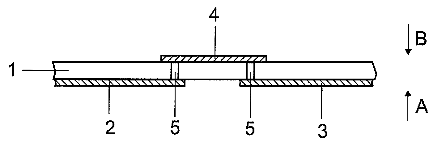
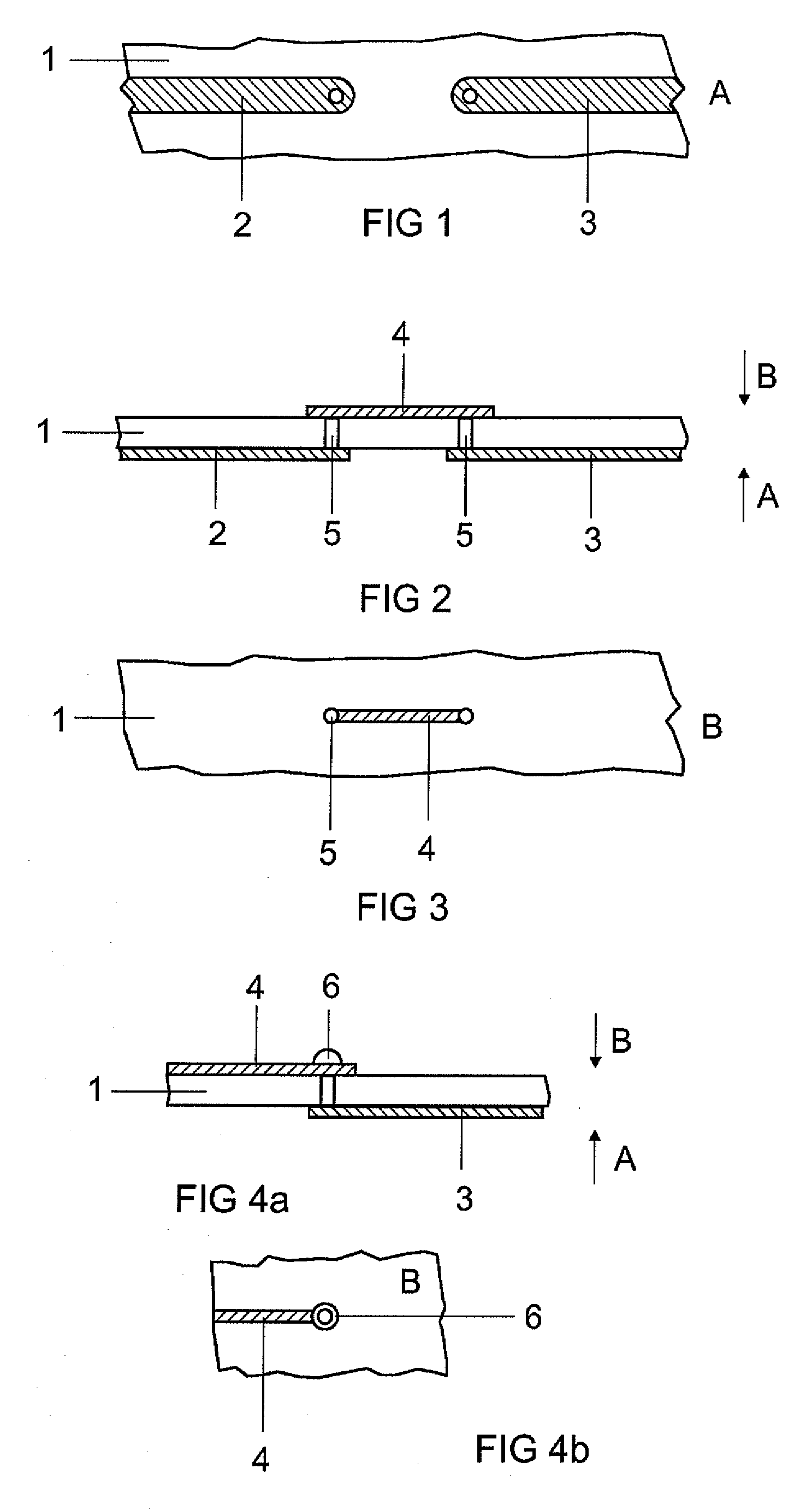
[0025]As can be seen in FIGS. 1-3, the conductor track fuse is divided into two sections: the supply line part 2, 3 running on one side of the printed circuit board, and the fusible link part 4 running on the other side of the printed circuit board. The two parts are connected by means of two through contacts 5. The through contacts 5 can be pure vias, as illustrated in FIG. 2, but they can also be formed by a wired component, e.g. a resistor having a high resistance.

[0026]As shown in FIGS. 4a and 4b, the through contact 5 is preferably embodied as a pure via, and covered with an adhesive spot 6 composed of SMD adhesive on the side of the fusible link 4. Said adhesive spot can be applied in the course of SMD component mounting, with the result that an additional work operation is not necessary. The adhesive spot 6 additionally contributes to the fact that, in the case of a short circuit, the plasma 21 cannot burn through the through contact.

[0027]For the case where two conductor tra...


PUM


Abstract

A double-sided printed circuit board may include: electrical conductor tracks fitted thereon and serving for electrically connecting components mounted on the printed circuit board, which has at least one conductor track fuse in the form of a conductor track with a fusible link part, wherein, upon the occurrence of an abnormal operating state, in particular an electrical short circuit, the electric circuit is interrupted by melting and evaporation of the fusible link part and plasma arises upon the evaporation of the fusible link part, wherein the fusible link part lies on the other side of the printed circuit board with respect to the supply line.

Description

TECHNICAL FIELD[0001]The invention relates to a double-sided printed circuit board comprising a strip conductor safety fuse in accordance with the preamble of patent claim 1.PRIOR ART[0002]In the event of an abnormal operating state, in particular in the event of a short circuit, the conductor track fuse of a printed circuit board has the task of rapidly and reliably interrupting the connection to the voltage supply. This is intended to prevent the short circuit from propagating on the printed circuit board and incurring further damage. Moreover, the early response of the conductor track fuse is intended to prevent a power supply circuit-breaker from being triggered.[0003]For this purpose, a specific conductor track section on the printed circuit board is often embodied as a fusible link. This conductor track section has a cross section which is constricted in comparison with the other conductor tracks on the printed circuit board and which is intended to melt in a controlled fashio...

Claims


Application Information

Patent Timeline
IPC IPC(8): H02H5/04
CPCH01H85/046H01H85/38H01H85/463H05K2203/095H01H2085/383H05K1/0293H05K2201/10181H01H2085/0275H05K1/02
Inventor CASPER, GUENTHERWERNI, HORST
Owner ABL IP HLDG
Why Eureka
Try Eureka