Power storage device

Inactive Publication Date: 2014-04-10
SEMICON ENERGY LAB CO LTD
View PDF5 Cites 6 Cited by
  • Summary
  • Abstract
  • Description
  • Claims
  • Application Information

AI Technical Summary

Benefits of technology

The present invention aims to provide a power storage device with better safety and longer life span. This can be achieved by improving the design of the device to minimize risks and prevent operational failures.

Problems solved by technology

However, if this SUS directly contacts with a positive electrode current collector formed using aluminum or the like in an ionic liquid that is a solvent of an electrolyte solution, elution of the positive electrode current collector occurs due to contact between different kinds of metals; thus, a problem of shortening cycle life of the battery arises.

Method used


Image

  • Power storage device
  • Power storage device
  • Power storage device

Examples


embodiment 1

[0027]A structure of a power storage device of one embodiment of the present invention and a method for manufacturing the power storage device will be described with reference to drawings. An example in which the power storage device is a lithium-ion secondary battery will be described below.

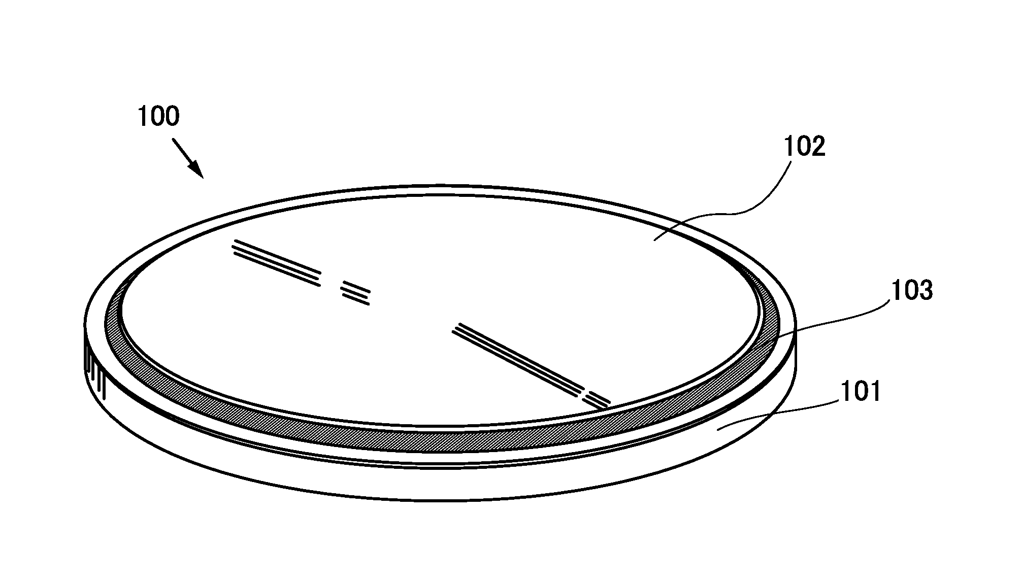
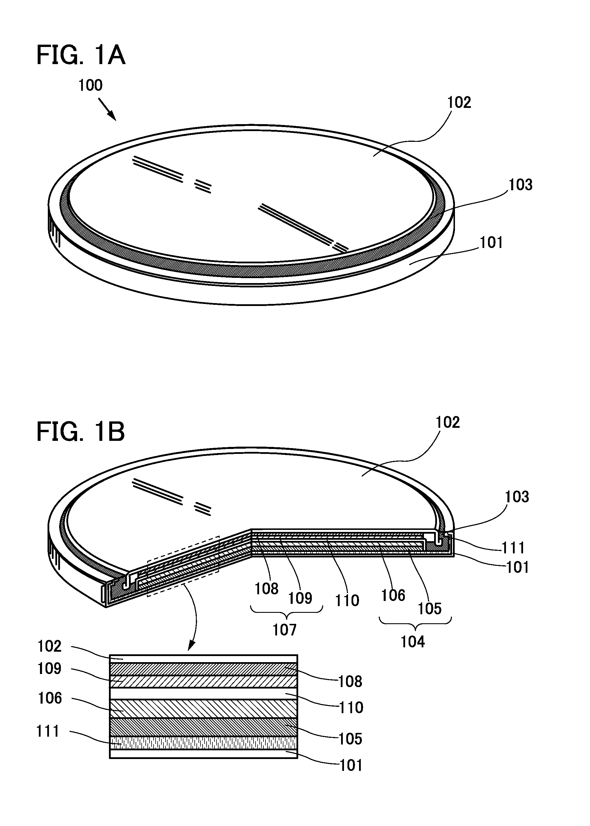
[0028]FIG. 1A is an external view of a coin-type power storage device 100, and FIG. 1B is a cross-sectional view thereof.

[0029]The coin-type power storage device 100 includes a positive electrode can 101 that is part of an exterior body and also serves as a positive electrode terminal, a negative electrode can 102 that is part of an exterior body and also serves as a negative electrode terminal, a gasket 103 formed using polypropylene or the like, a protective component 111 covering the positive electrode can 101, and an electrolyte solution (not illustrated) provided in a space surrounded by the positive electrode can 101 and the negative electrode can 102. Note that an ionic liquid is used as ...

embodiment 2

[0101]A structure of a power storage device of one embodiment of the present invention will be described with reference to the drawings. An example in which the power storage device is a lithium-ion secondary battery will be described below.

[0102]An example of a cylindrical power storage device will be described with reference to FIGS. 4A and 4B. As illustrated in FIG. 4A, a cylindrical power storage device 300 includes a positive electrode cap (also referred to as battery cap) 301, which is part of an exterior body, on the top surface and a battery can 302, which is part of the exterior body, on the side surface and bottom surface. The positive electrode cap 301 and the battery can 302 are insulated from each other by a gasket (also referred to as insulating gasket) 310.

[0103]FIG. 4B is a diagram schematically illustrating a cross section of the cylindrical power storage device. Inside the battery can 302 having a hollow cylindrical shape, a battery element in which a strip-shaped ...

embodiment 3

[0108]In this embodiment, a power storage device having a structure different from those of the power storage devices described in the above embodiment will be described. Specifically, descriptions will be given taking a lithium-ion capacitor and an electric double layer capacitor (EDLC) as examples.

[0109]A lithium-ion capacitor is a hybrid capacitor having a combination of a positive electrode of an electric double layer capacitor and a negative electrode of a lithium-ion secondary battery formed using a carbon material and is also an asymmetric capacitor where power storage principles of the positive electrode and the negative electrode are different from each other. The positive electrode forms an electrical double layer and enables charge and discharge by a physical action, whereas the negative electrode enables charge and discharge by a chemical action of lithium. In a lithium-ion capacitor, a negative electrode in which lithium is occluded in a negative electrode active materi...


PUM


Abstract

A power storage device with a higher degree of safety is provided. Further, a power storage device with improved cycle life is provided. In the power storage device, an ionic liquid as a solvent of an electrolyte solution, and an exterior body is covered with a conductive component so as to prevent direct contact between a positive electrode current collector and the exterior body. This suppresses elution of the positive electrode current collector due to contact between different kinds of metals and accordingly prevents a phenomenon in which the eluted metal of the positive electrode current collector is deposited on a negative electrode and the deposited metal comes in contact with a positive electrode. Thus, an internal short-circuit caused by the contact can be prevented.

Description

TECHNICAL FIELD[0001]The present invention relates to power storage devices. Note that the power storage device indicates all elements and devices which have a function of storing electricity.BACKGROUND ART[0002]A variety of power storage devices, for example, nonaqueous secondary batteries such as lithium-ion batteries (LIBs), lithium-ion capacitors (LICs), and air cells, have been actively developed in recent years. In particular, demand for lithium-ion secondary batteries with high output and high energy density has rapidly grown with the development of the semiconductor industry, for the uses of electric appliances, for example, portable information terminals such as mobile phones, smartphones, and laptop computers, portable music players, and digital cameras; medical equipment; and next-generation clean energy vehicles such as hybrid electric vehicles (HEVs), electric vehicles (EVs), and plug-in hybrid electric vehicles (PHEVs). The lithium-ion batteries are essential for today...

Claims


Application Information

Patent Timeline
IPC IPC(8): H01G9/035H01G11/62H01M2/24H01M50/119H01M50/529H01M50/571
CPCH01G9/035H01G11/62H01M2/24H01G11/70H01G11/82H01M4/661H01M10/052H01M10/058H01M10/0585H01M10/0587H01M10/0427H01M10/0431H01M50/529H01M50/119Y02T10/70Y02E60/10Y02P70/50Y02E60/13
Inventor ISHIKAWA, JUNITO, KYOSUKEYOKOI, RIE
Owner SEMICON ENERGY LAB CO LTD
Why Eureka
Try Eureka