Blanking panel for equipment rack or enclosure

a blanking panel and equipment rack technology, applied in the direction of support structure mounting, printed circuit board receptacles, show hangers, etc., can solve the problems of inconvenient installation of a number of blanking panels during the configuration of an equipment rack, time-consuming and difficult, etc., to achieve convenient and quick installation, and convenient and quick installation

Active Publication Date: 2009-03-24
AMERICA POWER CONVERSION CORP
View PDF20 Cites 74 Cited by
  • Summary
  • Abstract
  • Description
  • Claims
  • Application Information

AI Technical Summary

Benefits of technology

[0008]Another object of the invention includes providing a blanking panel configured to form an air seal between adjacent blanking panels and equipment components when installed into a rack or enclosure to help to reduce or prevent mixing of hot exhaust air with cooling air.
[0037]A blanking panel can be constructed and arranged to define any height, e.g., 1U, 2U, 3U, 4U, etcetera, or any fractional U height, to help to provide flexibility and convenience with respect to configuring a rack or enclosure and filling-in vacant sections of the rack or enclosure. In particular, a blanking panel with a nominal 1U height helps to optimize flexibility and convenience. One or more 1U blanking panels may be easily and quickly installed into and removed from a rack to fill-in vacant sections created as a result of reconfiguring or rearranging the rack and to thereby accommodate vacant sections having any U height. In addition, using 1U blanking panels eliminates the need to locate a sufficient number and variety of blanking panels that collectively have the specific U height needed to fill-in a vacant section. The 1U blanking panel can thereby help to provide efficiency during installation of equipment components and configuration of a rack.

Problems solved by technology

In many instances, equipment racks and enclosures are not fully configured from top to bottom with rack-mounted components, resulting in vacant sections of an equipment area defined by the rack or enclosure.
Proper installation of a number of blanking panels during configuration of an equipment rack can be inconvenient, time-consuming and difficult as a result of the number of screw and nut combinations that need to be manipulated to attach or to remove several blanking panels.
Prior art blanking panels may be configured with a height of several U; however, large blanking panels do not necessarily provide convenience or flexibility with respect to configuring and rearranging an equipment rack.
Installation of blanking panels to reconfigure or rearrange a rack can be similarly time-consuming and difficult.
Such blanking panels are not configured, for instance, to reduce or eliminate gaps between installed blanking panels and equipment components and, therefore, have little or no effect in preventing mixing of hot exhaust air with cooling air within a rack.
Any effect such designs have on air circulation is minimal and merely consequential.
Such designs are relatively expensive to manufacture and to ship.
In addition, metal blanking panels are prone to scratching and other surface abrasion, and can be easily bent during shipping, handling and installation.

Method used


Image

  • Blanking panel for equipment rack or enclosure
  • Blanking panel for equipment rack or enclosure
  • Blanking panel for equipment rack or enclosure

Examples


Embodiment Construction

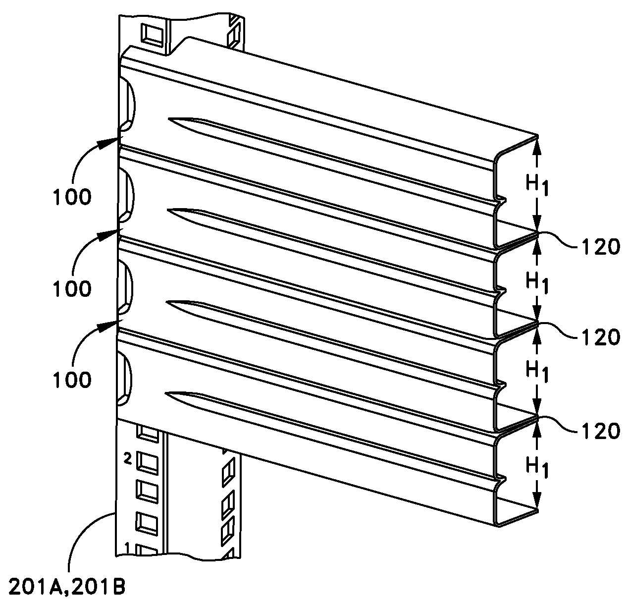
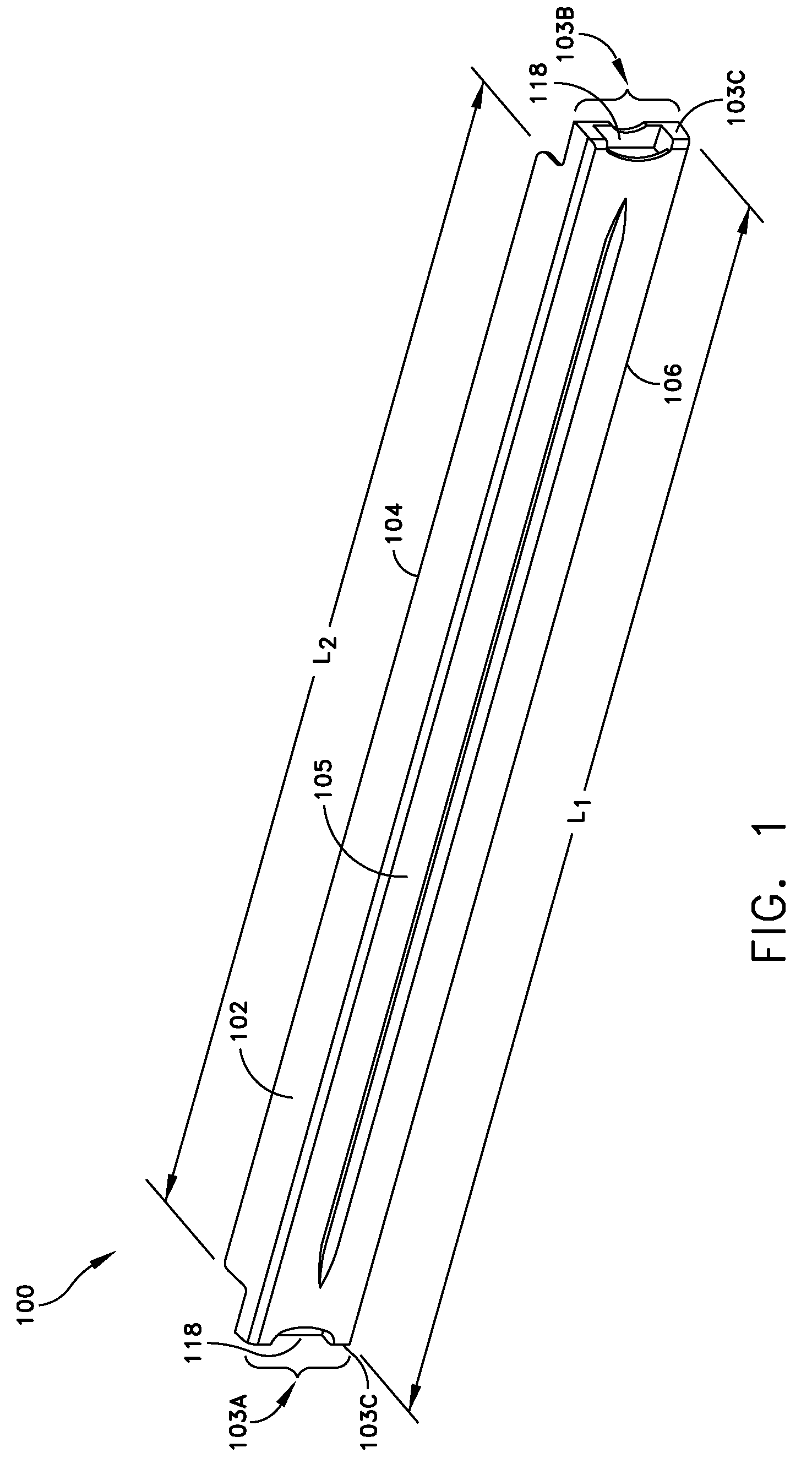
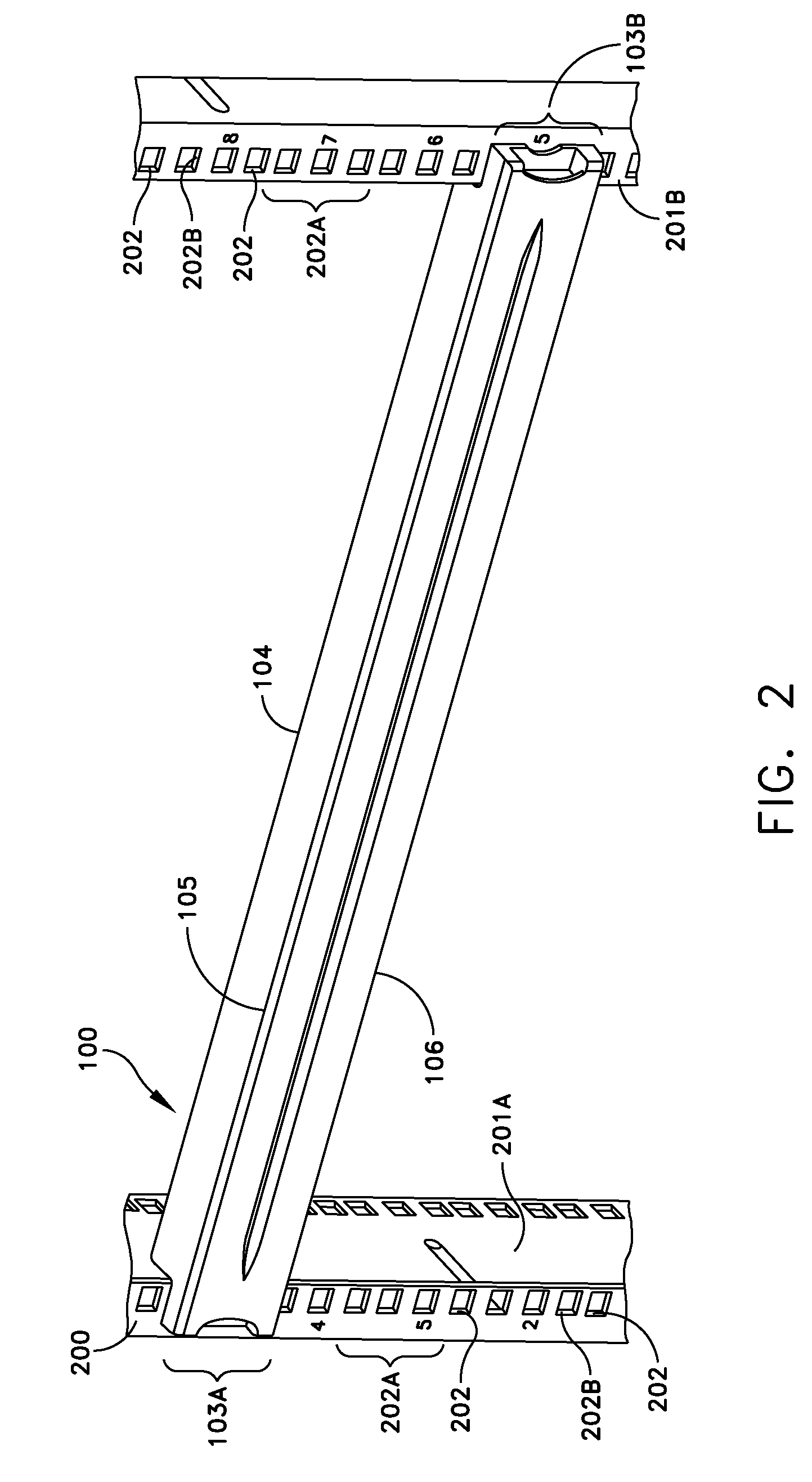
[0073]Embodiments of the invention provide a filler or blanking panel configured for attachment to vertical mounting flanges or rails of an equipment rack or enclosure used to contain equipment including servers, networking equipment, information technology equipment, communications equipment and other electronic components. The blanking panel includes an elongated panel body defining along each end an attachment configuration. Each attachment configuration is constructed and arranged to facilitate tool-less installation and removal of the blanking panel to a pair of adjacent vertical mounting flanges or rails of an equipment rack or enclosure. Each attachment configuration may include one or more retention tabs, retention hooks, alignment pegs, or one or more similar configurations, and any combinations of such tabs, hooks, pegs and configurations. The retention tabs, hooks, and alignment pegs are constructed and arranged to facilitate tool-less installation and removal of the blan...


PUM

PropertyMeasurementUnit
angleaaaaaaaaaa
lengthaaaaaaaaaa
forceaaaaaaaaaa

Abstract

A blanking panel is provided for use with equipment racks or enclosures that house electronic components, and is configured to facilitate installation of the panel with a pair of vertical mounting rails or flanges of a rack or enclosure without the use of tools or other hardware. The blanking panel is constructed of one or more materials and / or defines one or more configurations such that when the blanking panel is installed into a rack or enclosure, portions of a body of the blanking panel interface with a surface of an equipment component or another blanking panel installed above or below the blanking panel to thereby form an air seal there between, which helps to reduce or prevent hot exhaust air from mixing with cooling air within a rack or enclosure, and further helps to reduce or prevent cooling air from bypassing equipment components.

Description

FIELD OF THE INVENTION[0001]A filler or blanking panel is provided for use with an equipment rack or enclosure.BACKGROUND OF THE INVENTION[0002]Equipment racks and enclosures for housing electronics help to integrate a variety of different types of equipment including servers, networking equipment, power supplies, storage systems and other electronics equipment, as well as help to configure and manage an IT environment. Availability and flexibility with respect to configuring a rack environment and, in particular, with respect to reconfiguring or relocating an installed rack are essential for efficient and practical management of equipment rooms and data centers. In many instances, equipment racks and enclosures are not fully configured from top to bottom with rack-mounted components, resulting in vacant sections of an equipment area defined by the rack or enclosure. Typically, blanking panels are attached to mounting flanges or rails of a rack or enclosure to block or fill-in such ...

Claims


Application Information

Patent Timeline
Patent Type & Authority Patents(United States)
IPC IPC(8): A47F7/00
CPCH05K7/1425Y10T29/49826
Inventor RASSMUSSEN, NEILSPITAELS, JAMES S.MATTLIN, JEFFREY LEEZIEGLER, WILLIAM
Owner AMERICA POWER CONVERSION CORP
Why Eureka
Try Eureka