Fluid conduit system and fittings therefor

a technology of fluid conduit and fittings, which is applied in the direction of hose connections, manufacturing tools, mechanical apparatus, etc., can solve the problems of increasing the difficulty of making sweat solder connections, affecting the service life of the system,

Inactive Publication Date: 2009-04-14
MUELLER IND INC
View PDF37 Cites 57 Cited by
  • Summary
  • Abstract
  • Description
  • Claims
  • Application Information

AI Technical Summary

Problems solved by technology

Modern changes to various plumbing codes, which mandate lead-free solders and water soluble fluxes, have, however, greatly increased the difficulty in making sweat solder connections as these lead-free solders and water soluble fluxes tend to be less tolerant of certain variables (e.g., the presence of oxidation or the use of excessive heat) than the lead-based solders and acid-based fluxes that had been previously used.
Furthermore, the sweat soldering task is relatively time consuming as compared to the crimp-type connections that are employed in a PEX (i.e., cross-linked polyethylene) system.
This system, however, is known to suffer from several drawbacks.
One such drawback concerns the sealing of the fitting to the outside surface of the copper tubing.
It is well known in the art that the outside surface of a copper tube is relatively susceptible to imperfections during its formation via extrusion, such as gouges or scratches, as well as relatively susceptible to damage during shipping and storage.
As such imperfections and damage may adversely affect the ability of the fittings to seal against the outer surface of the tubing, manufacturers of the copper tubing typically subject the extruded sticks of tubing to an eddy current test to verify the integrity of each stick's outside surface.
This testing is costly and as we have found, leaks are possible even when the tubing conforms to published standards.
Accordingly, it appears that a relatively time consuming manual inspection must be made of each tube prior to its coupling to a fitting.
Another drawback concerns the incompatibility of the known systems with lengths of annealed copper tubing.
In this regard, the annealed copper tubing is readily deformable so that the crimping process fails to secure the fitting and the annealed copper tubing together.

Method used


Image

  • Fluid conduit system and fittings therefor
  • Fluid conduit system and fittings therefor
  • Fluid conduit system and fittings therefor

Examples


Embodiment Construction

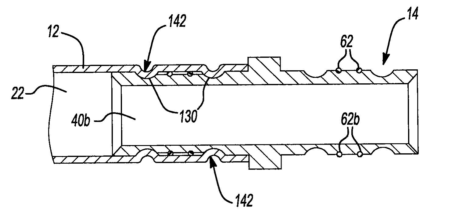
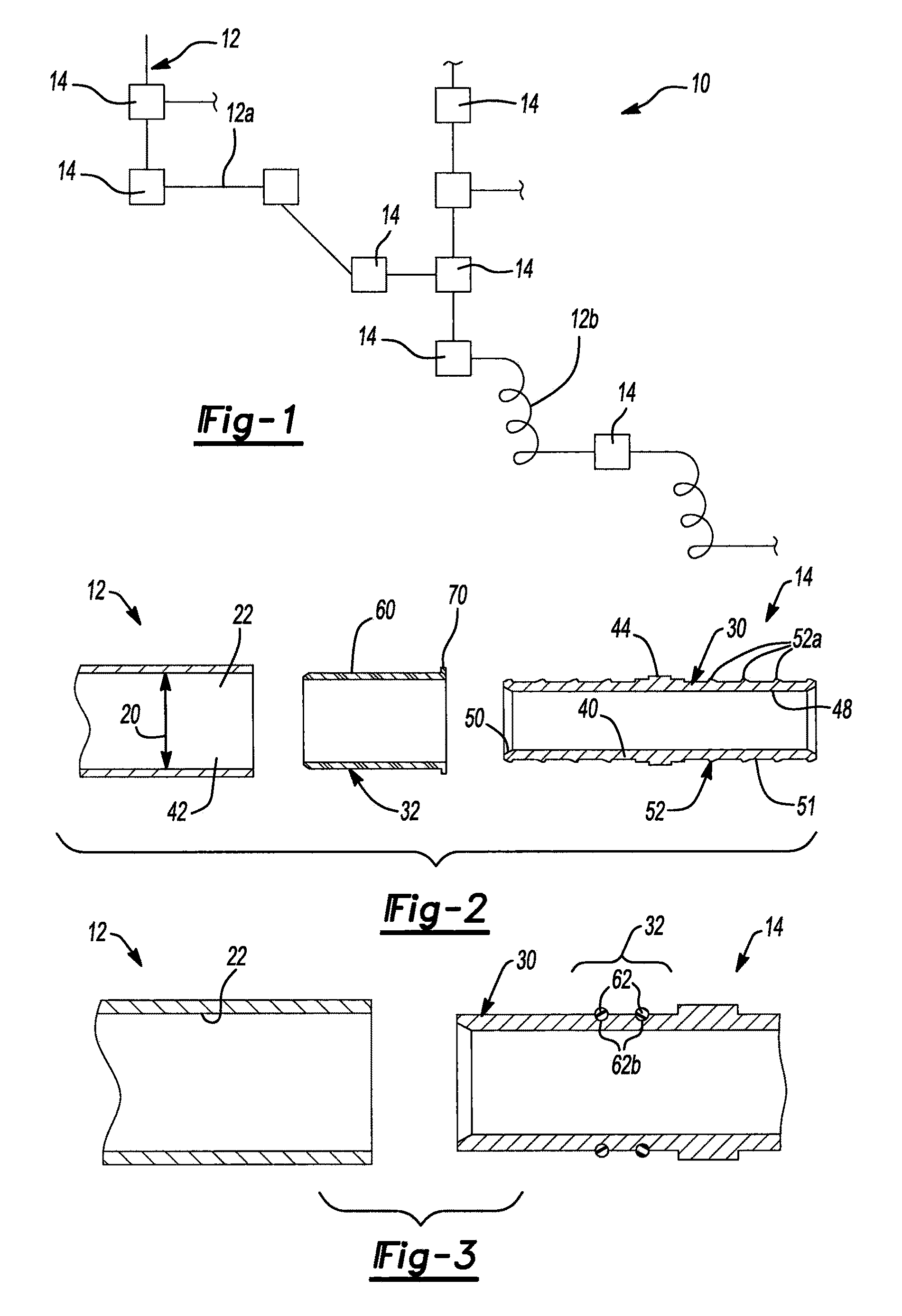
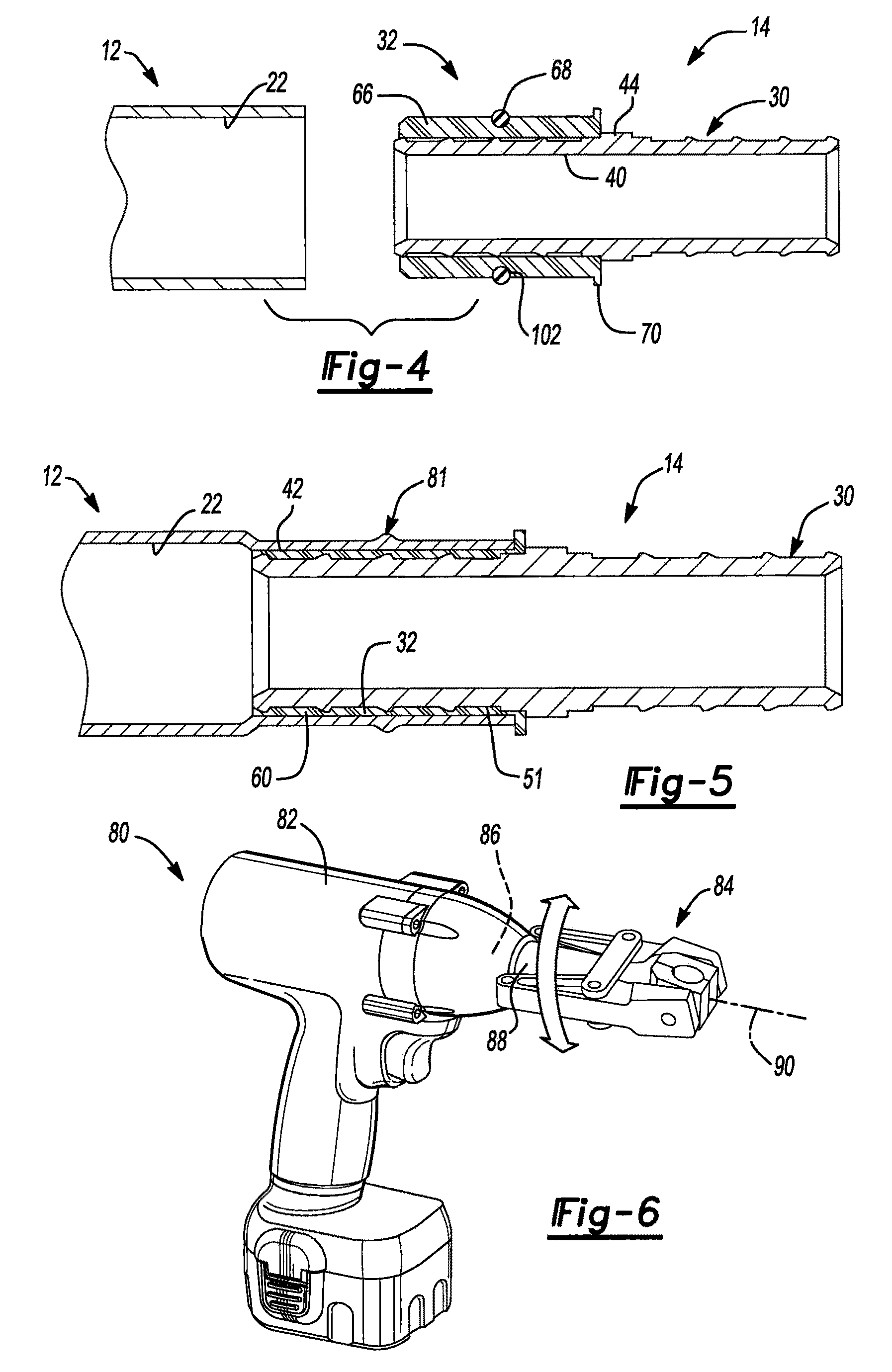
[0038]With reference to FIG. 1 of the drawings, an exemplary fluid conduit system constructed in accordance with the teachings of the present invention is generally indicated by reference numeral 10. The fluid conduit system 10 is illustrated to include a plurality of tubes 12 and a plurality of fittings 14 that are employed to join the tubes 12 to one another. In the example provided, the fluid conduit system 10 is employed to route and deliver potable water and as such, the tubes 12 may be constructed of copper and include conventional commercially available hard drawn tubing sticks 12a and conventional soft tubing 12b (also referred to herein as “annealed”, or “flexible metal” tubing) of the type that is commercially available in a coiled form from sources such as Mueller Industries, Inc. of Memphis, Tenn. Those skilled in the art will appreciate, however, that the tubes 12 may be made out of any suitable metal or plastic material and that the teachings of the present invention h...


PUM

PropertyMeasurementUnit
internal diameteraaaaaaaaaa
inner diameteraaaaaaaaaa
distanceaaaaaaaaaa

Abstract

A fluid conduit system that employs fittings having ends with a structural portion and a seal portion. The ends of the fittings are inserted into a tube, which may be a hard, i.e., rigid, or soft, i.e., flexible, tube. The seal portion sealingly engages the inner diameter of the tube upon its insertion into the tube. The tube is deformed to prevent the fitting from being withdrawn from the tube; the portion of the tube in the immediate vicinity of each seal that forms the seal portion is not deformed. A method for forming a fluid conduit system is also provided.

Description

CROSS-REFERENCE TO RELATED APPLICATIONS[0001]This application claims the benefit of U.S. Provisional Application Ser. No. 60 / 470,599 filed May 15, 2003.FIELD OF THE INVENTION[0002]The present invention generally relates to fluid conduit systems that may be employed, for example, for routing and delivering potable water, gases or chemicals.BACKGROUND OF THE INVENTION[0003]Sweat soldering has long been used for the supply and distribution of potable water, especially in single family residential constructions, due to its durability and the relative ease with which solder connections were made. Modern changes to various plumbing codes, which mandate lead-free solders and water soluble fluxes, have, however, greatly increased the difficulty in making sweat solder connections as these lead-free solders and water soluble fluxes tend to be less tolerant of certain variables (e.g., the presence of oxidation or the use of excessive heat) than the lead-based solders and acid-based fluxes that...

Claims


Application Information

Patent Timeline
Patent Type & Authority Patents(United States)
IPC IPC(8): F16L13/14B25B27/10
CPCB25B27/10F16L13/141F16L13/143
Inventor JAMISON, TOMMY LDENNIS, H. GLENNGAY, KEVIN
Owner MUELLER IND INC
Why Eureka
Try Eureka