Optical output control method for use in optical transmission node and optical output control apparatus for use in the same

a control method and control apparatus technology, applied in the direction of transmission monitoring, electromagnetic repeaters, instruments, etc., can solve the problems of automatic reduction of optical output, inability to perform power measurement or the like, and inability to perform power measurement, etc., to achieve remarkable improvement of the security environment of a worker such as a maintenance engineer

Active Publication Date: 2009-04-14
FUJITSU LTD
View PDF17 Cites 5 Cited by
  • Summary
  • Abstract
  • Description
  • Claims
  • Application Information

AI Technical Summary

Benefits of technology

[0035]According to the present invention, if optical output power measurement or the like is requested for the optical transmission node and the automatic optical output control inhibition status is set to the optical transmission node, and thereafter the optical transmission path (transmission path fiber) restores its original status (i.e., the fiber is reconnected to the node), the automatic optical output control inhibition status is automatically canceled. Therefore, even if the transmission fiber is thereafter pulled out from the node, the automatic optical output control will be activated and light can be prevented from being inadvertently released from the fiber at a high power level. Accordingly, security environment for a worker such as a maintenance engineer can be remarkably improved.

Problems solved by technology

As a consequence, the optical output will be automatically decreased owing to the APSD control, with the result that it becomes unable to perform power measurement or the like.
Therefore, the station 100A halts the optical output thereof owing to the APSD control and with the result that it becomes unable to perform power measurement.
However, even if the APSD control is arranged to restore automatically within a period of time of several minutes counted by the time as described above, this APSD control arrangement cannot always handle all possible accidental cases.
In such a case, there is a fear that an optical output with a high power can be outputted.

Method used


Image

  • Optical output control method for use in optical transmission node and optical output control apparatus for use in the same
  • Optical output control method for use in optical transmission node and optical output control apparatus for use in the same
  • Optical output control method for use in optical transmission node and optical output control apparatus for use in the same

Examples


first embodiment

[A] Description of First Embodiment

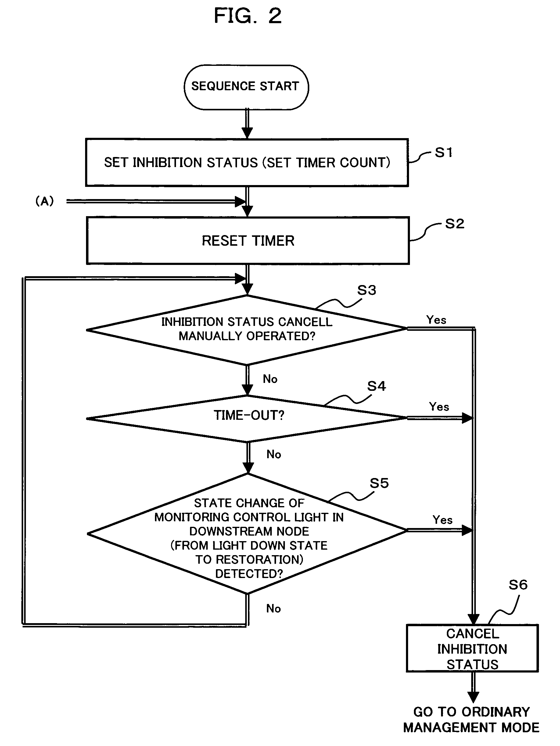
APSD Inhibit Automatic Cancellation

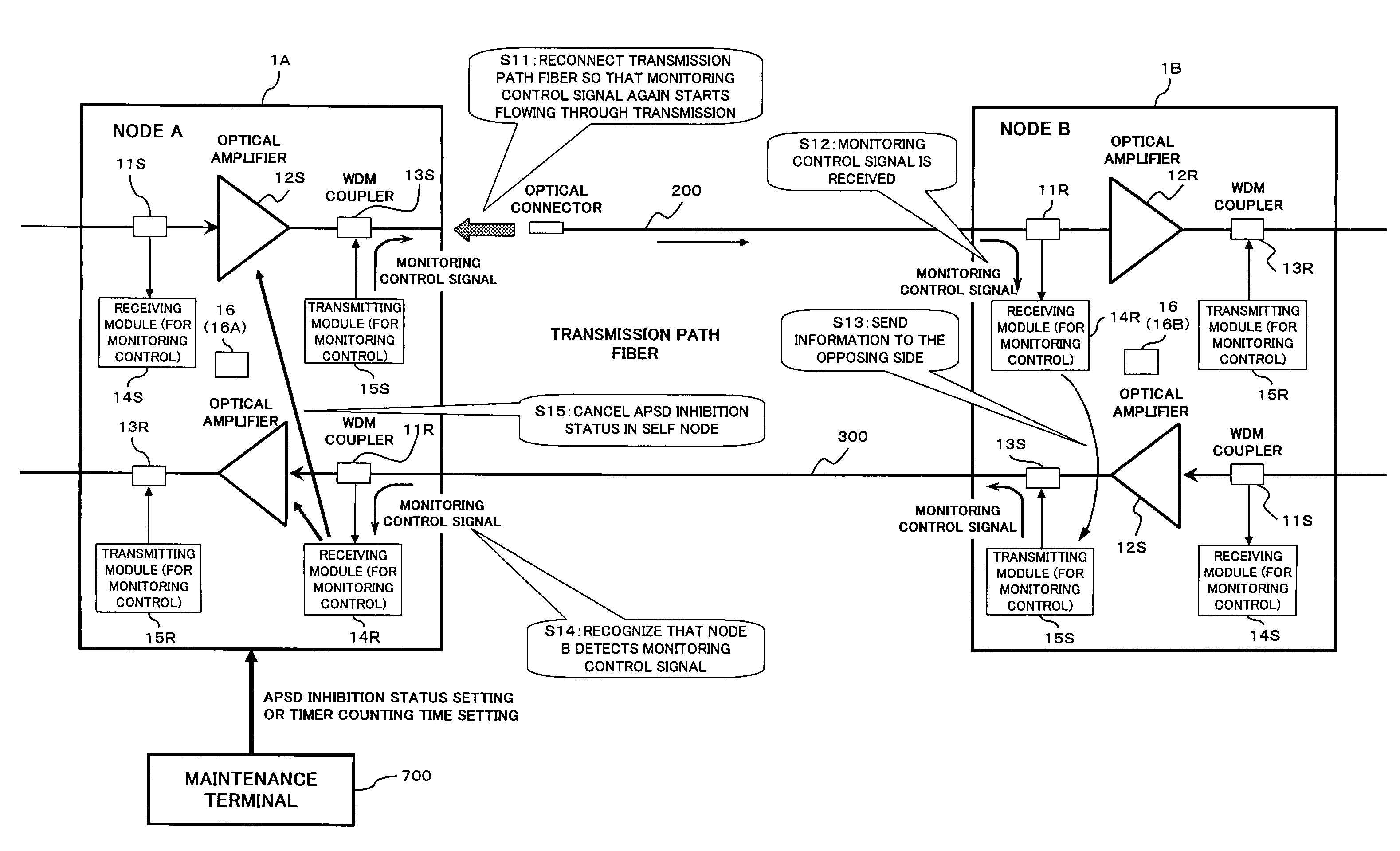
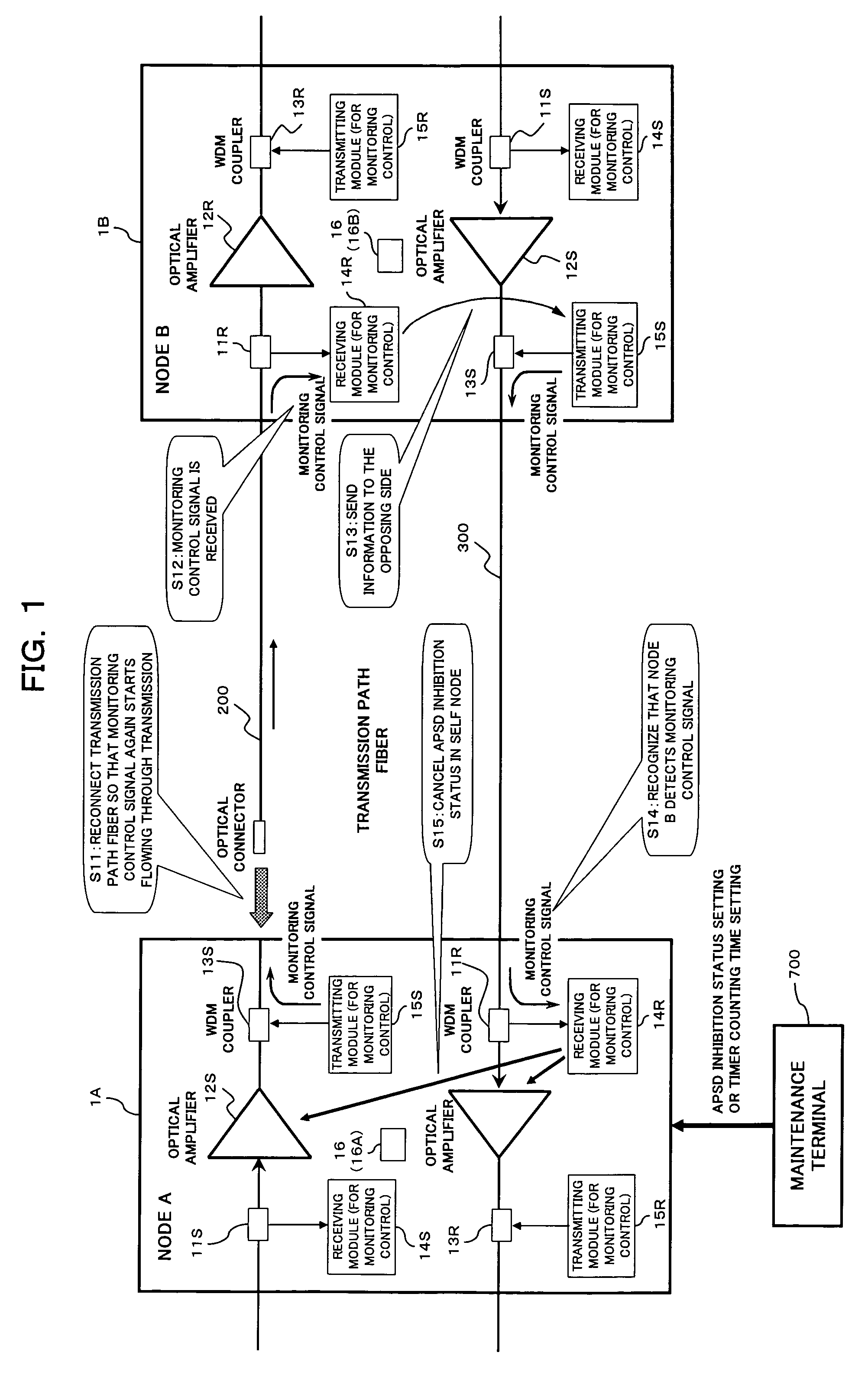
[0049]FIG. 1 is a block diagram showing an arrangement of a WDM optical transmission system as a first embodiment of the present invention. Similarly to the aforesaid system described with reference to FIG. 10, the WDM optical transmission system shown in FIG. 1 also is arranged to include an optical transmission apparatus (optical node) 1A (station A) and an optical transmission apparatus (optical node) 1B (station B) which are cross-connected to each other through a couple (two) of optical transmission paths (transmission path fibers) 200 and 300. Thus, bidirectional communication can be performed in the arrangement.

[0050]Also in the present embodiment, each of the optical transmission apparatus (hereinafter sometimes simply referred to as “node” or “station”) 1A and 1B has a symmetrical arrangement. That is, each of the optical transmission apparatus has, as a transmission system, WDM couplers 11S and 13S, an o...

second embodiment

[B] Description of Second Embodiment

Transmission Path Fiber Open Real Time Management

[0096]When the inhibition status is taken place in the upstream-side station 1A (1B), the time setting of the restoration timer can be arbitrarily performed from the maintenance terminal 700. The restoration timer will star time counting from the timing point when the inhibition status is taken place. In this case one situation can be considered that when the inhibition status is taken place, the station is connected with the transmission path fiber 200 (300) (i.e., the station is brought into the ordinary management mode). In this case, light will emit from the fiber during a time period corresponding to a time interval, i.e., from a timing point when the timer has time set to a timing point when the transmission path fiber 200 (300) is pulled out.

[0097]In this case, if the timer setting time is reasonably short time, there will be no serious problem caused. However, if the timer setting time is ex...


PUM


Abstract

In an optical transmission node network in which a first optical transmission node is connected with a second optical transmission nodes through an optical fiber cable and automatic optical output (APSD: Automatic Power Shut-Down) control is activated, after the APSD control is brought into an inhibited status, if an optical conduction to the second optical transmission node is detected, the APSD control inhibited status is canceled. In this way, if an optical transmission fiber is resorted (reconnected) after optical output power measurement or the like is carried out, the APSD control inhibition status (invalid status) is canceled for automatically restoring the APSD control activated status. Thus, optical output can be prevented from being inadvertently emitted at a high energy level from the optical fiber cable.

Description

BACKGROUND OF THE INVENTION[0001](1) Field of the Invention[0002]The present invention relates to an optical output control method for use in an optical transmission node and an optical output control apparatus for use in the same. In more particularly, the present invention relates to a technology suitable for use in an optical transmission node with an automatic optical output control (APSD: Automatic Power Shut-Down) function which controls, in response to a reception of optical path cut (light down) detecting information from another optical transmission node, the optical output therefrom to decrease or halt.[0003](2) Description of Related Art[0004]FIG. 10 is a block diagram showing one example of a conventional WDM (Wavelength Division Multiplex) optical transmission system. As shown in FIG. 10, the WDM optical transmission system comprises an optical transmission station (optical transmission node) 100A (station A) and an optical transmission station (optical transmission nod...

Claims


Application Information

Patent Timeline
Patent Type & Authority Patents(United States)
IPC IPC(8): H04B10/02H04B10/00H04B10/03H04B10/07H04B10/071H04B10/077H04B10/29H04J14/00H04J14/02
CPCH04B10/0793H04B2210/08
Inventor OHTANI, TOSHIHIROSATO, MASAKI
Owner FUJITSU LTD
Why Eureka
Try Eureka