Test apparatus for testing operation of a printed circuit board

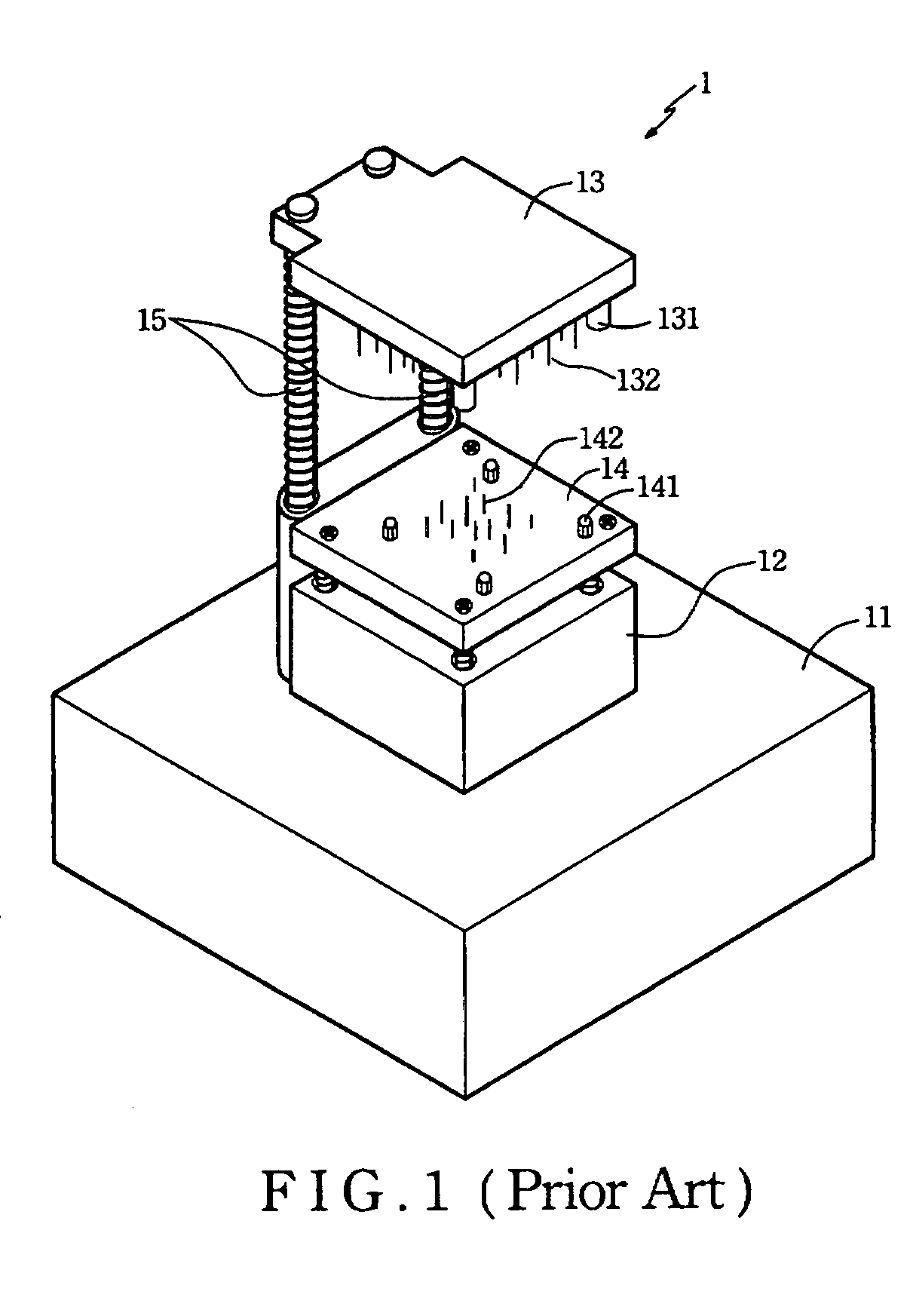
a technology for testing apparatus and printed circuit boards, which is applied in the field of test apparatus, can solve problems such as bending of printed circuit boards and soldering ball rupture, and achieve the effect of removing the defect of bending

Inactive Publication Date: 2009-04-21
INVENTEC APPLIANCES CORP
View PDF8 Cites 3 Cited by
  • Summary
  • Abstract
  • Description
  • Claims
  • Application Information

AI Technical Summary

Benefits of technology

[0012]Preferably, the lower spacer disc in the aforesaid test apparatus has an upper surface greater than a lower surface of the upper spacer disc. Generally, the electrical contacts of the printed circuit board under test are concentrated at the middle portion thereof so as to reserve the outer peripheral portion for soldering with the other electronic components in case the circumstance demands in the future. The purpose of designing a smaller surface area in the upper spacer disc relative to the lower spacer disc is to avoid undesired pressing on the outer peripheral portion of the printed circuit board during the testing operation, thereby eliminating the defect of bending in the printed circuit board generally encountered when using the prior test apparatus.

Problems solved by technology

The board displacement during the testing operation may result in misalignment between the probes of the upper and lower plate with respect to the electrical contacts of the printed circuit board, thereby causing bending of the printed circuit board, which, in turn, affects some components (such as Ball Grid Array) mounted thereon in addition the inaccurate test result and rupture at the soldering balls.

Method used


Image

  • Test apparatus for testing operation of a printed circuit board
  • Test apparatus for testing operation of a printed circuit board
  • Test apparatus for testing operation of a printed circuit board

Examples


Embodiment Construction

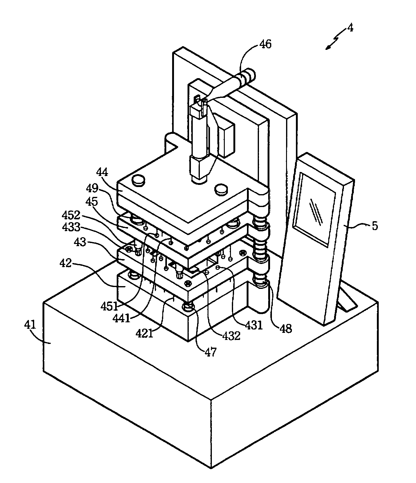
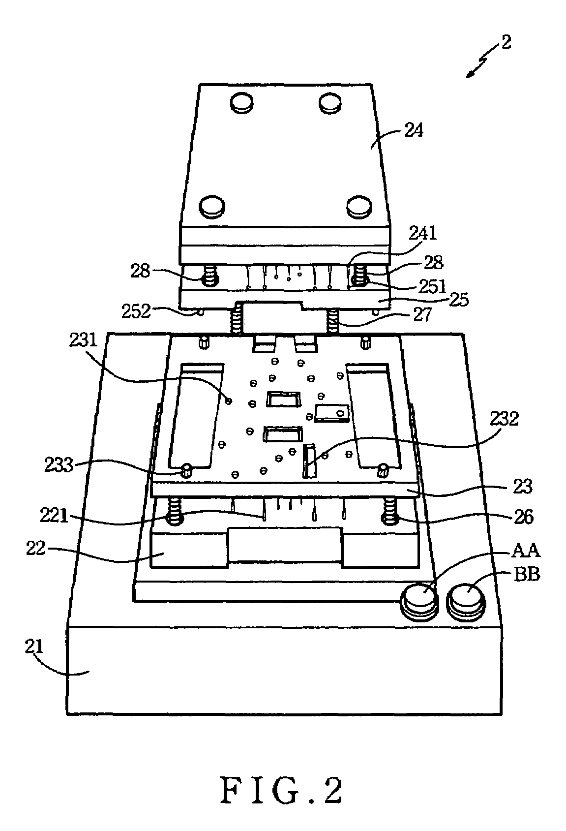
[0021]Referring to FIG. 2, the first preferred embodiment of a test apparatus in accordance with the present invention is shown for testing operation of a printed circuit board (not visible), and includes a bottom seat 21, a lower plate 22, a lower spacer disc 23, an upper plate 24, an upper spacer disc 25 and a two-step driving mechanism. Note that the test operation of the printed circuit board is conducted in the two-step manner. In this embodiment, the two-step driving mechanism is not visible since the same is mounted within the bottom seat 21.

[0022]The lower plate 22 is coupled operably onto the bottom seat 21, and has an upper surface formed with a plurality of first probes 221 for engaging the electrical contacts mounted on one side of the printed circuit board under test. The lower spacer disc 23 is coupled operably to the lower plate 22, and has a plurality of first openings 231 respectively aligned with the first probes 221 of the lower plate 22. The upper plate 24 is dis...


PUM


Abstract

A test apparatus includes lower and upper spacer discs for sandwiching and securing a printed circuit board therebetween, lower and upper plates, and a two-step driving mechanism. The lower and upper spacer discs are spaced apart from the lower and upper plates. Activation of the test apparatus in a first step results in relative movement between the spacer discs to sandwich the circuit board therebetween. Activation of the test apparatus in a second step results in relative movement between the lower and upper plates to sandwich the upper and lower spacer discs therebetween.

Description

FIELD OF THE INVENTION[0001]The present invention relates to a test apparatus. More particularly, the invention relates to a test apparatus for testing a printed circuit board in a two-step manner so as to improve the testing accuracy.BACKGROUND OF THE INVENTION[0002]During mass production of electronic products and prior to assembly of a printed circuit board therein, a test operation conducted onto the printed circuit board plays a major role. The electrical contacts of a respective printed circuit board must under go a testing operation in order ensure the circuit operation thereof. Only after assuring that there is no short circuit in the printed circuit board, the assembly of the former is carried out.[0003]FIG. 1 is a perspective view of a conventional test apparatus 1 in use presently in the assembly line. The test apparatus 1 accordingly includes a foundation 11, a base seat 12, an upper plate 13, a lower plate 14 and a coupler arm unit 15. The upper plate 13 is formed with ...

Claims


Application Information

Patent Timeline
Patent Type & Authority Patents(United States)
IPC IPC(8): G01R31/26G01R31/02
CPCG01R31/2805G01R31/2806
Inventor LEE, YUNG-TANGHO, HSIEN-TSUNG
Owner INVENTEC APPLIANCES CORP
Why Eureka
Try Eureka