RFID tag test antenna with two ports that excite perpendicular modes

a technology of perpendicular mode and antenna, which is applied in the direction of burglar alarm by hand-portable article removal, burglar alarm mechanical actuation, instruments, etc., can solve the problems that conventional readers are not capable of testing the antennas of tags separately, and conventional tags are not capable of facilitating such testing

Inactive Publication Date: 2009-05-26
SYMBOL TECH INC
View PDF3 Cites 28 Cited by
  • Summary
  • Abstract
  • Description
  • Claims
  • Application Information

AI Technical Summary

Problems solved by technology

However, conventional readers are not capable of separately testing the antennas of a tag that has multiple antennas.
Moreover, conventional tags are not capable of facilitating such testing.

Method used


Image

  • RFID tag test antenna with two ports that excite perpendicular modes
  • RFID tag test antenna with two ports that excite perpendicular modes
  • RFID tag test antenna with two ports that excite perpendicular modes

Examples


example rfid system embodiment

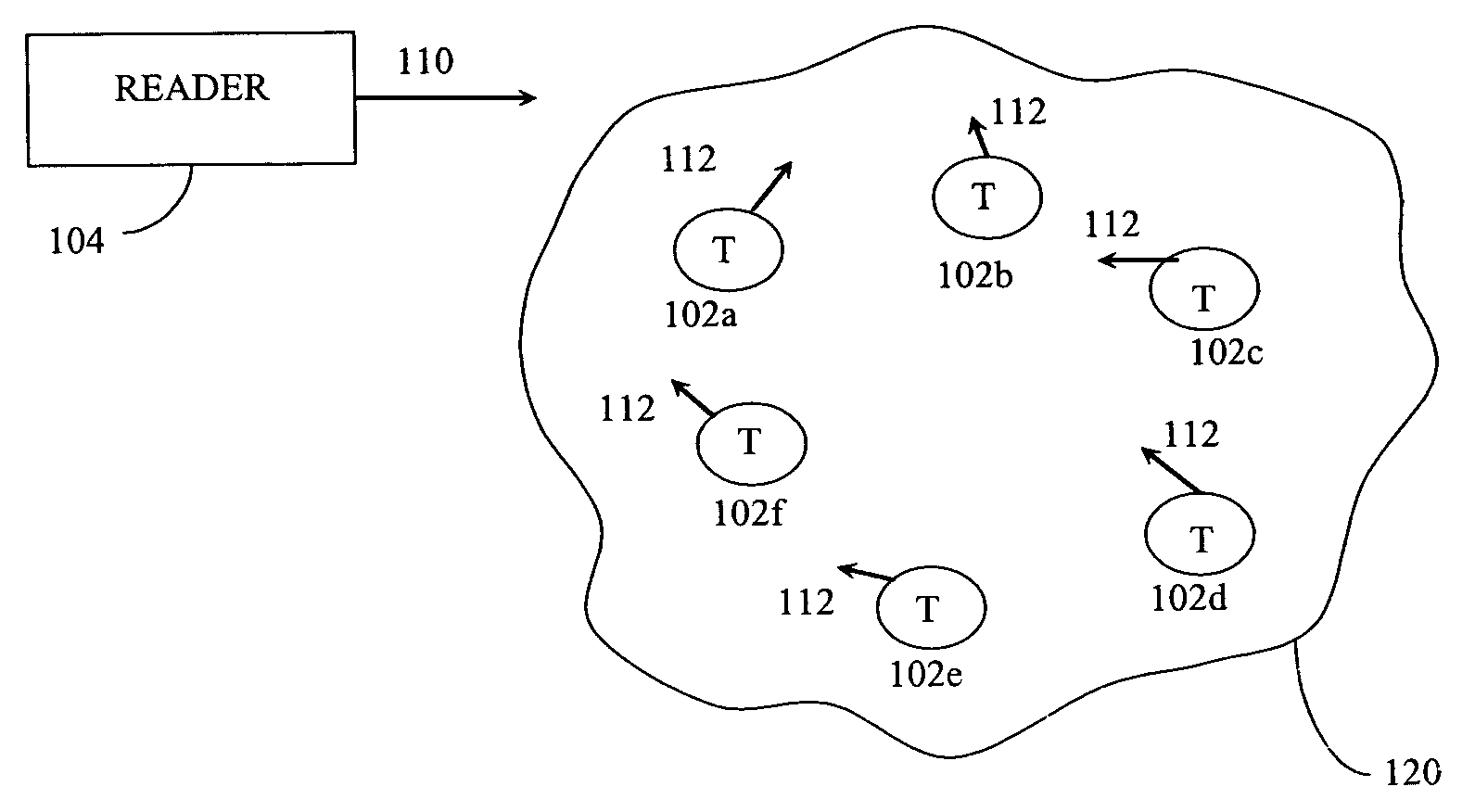
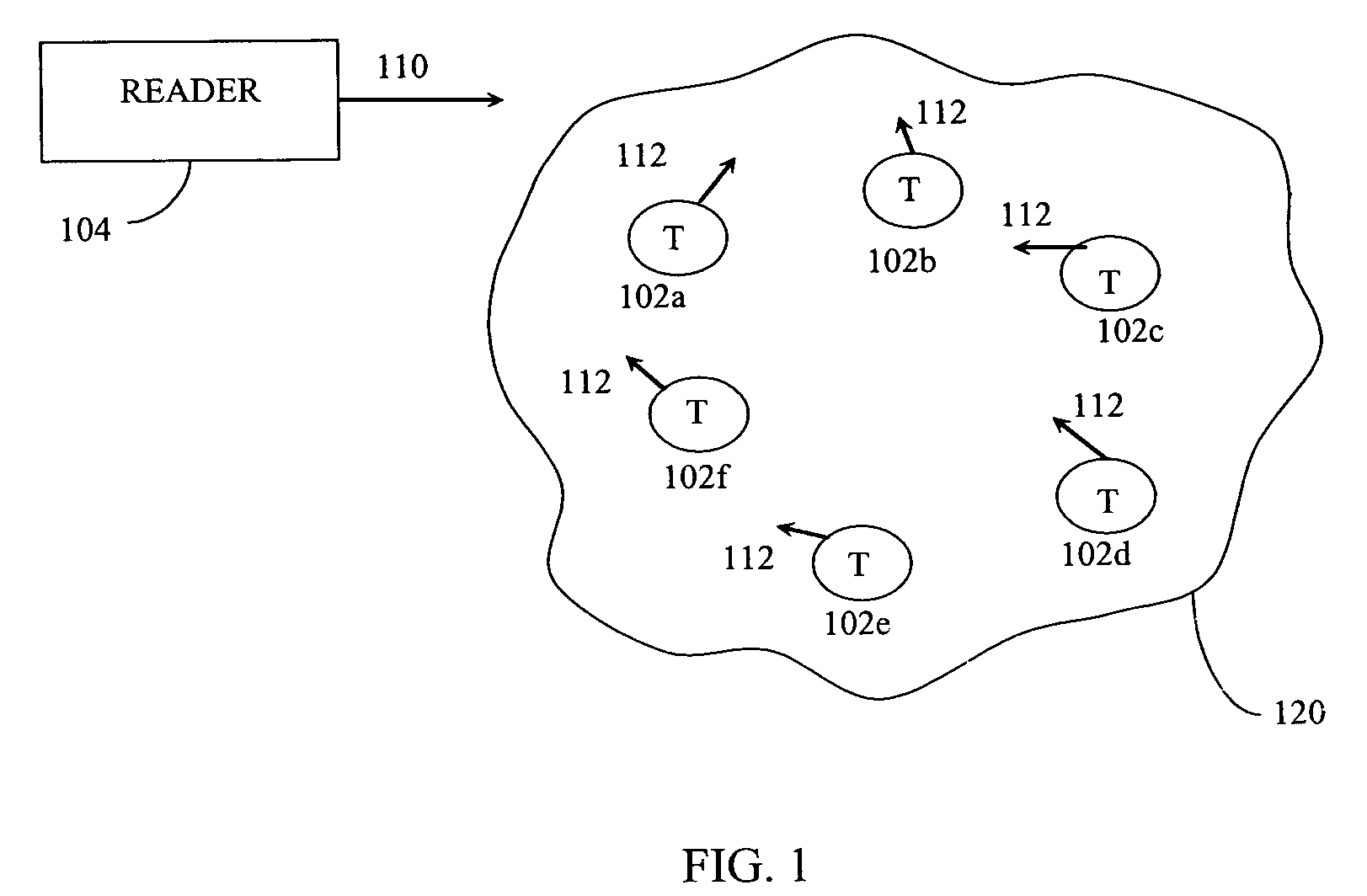
[0028]Before describing embodiments of the present invention in detail, it is helpful to describe an example RFIID communications environment in which the invention may be implemented. FIG. 1 illustrates an environment where RFID tag readers 104 communicate with an exemplary population 120 of REID tags 102. As shown in FIG. 1, the population 120 of tags includes seven tags 102a-102g. A population 120 may include any number of tags 102.

[0029]Environment includes one or more readers 104. A reader 104 may be requested by an external application to address the population of tags 120. Alternatively, reader 104 may have internal logic that initiates communication, or may have a trigger mechanism that an operator of reader 104a uses to initiate communication.

[0030]As shown in FIG. 1, reader 104 transmits an interrogation signal 110 having a carrier frequency to the population of tags 120. Reader 104 operates in one or more of the frequency bands allotted for this type of RF communication. ...


PUM


Abstract

Methods, systems, and apparatuses for RFID devices, such as tag test methods, are described. A tag of a strip of tags is positioned adjacent to an opening in an electrically conductive sheet, the tag having first and second orthogonally polarized antennas. A first RF test signal is transmitted through the opening to test the first antenna of the tag. The tag is positioned such that the first RF test signal has a polarization substantially the same as the first antenna and substantially orthogonal to a polarization of the second antenna. A second RF test signal is transmitted through the opening to test the second antenna of the tag. The tag is positioned such that the second RF test signal has a polarization substantially the same as the second antenna and substantially orthogonal to the polarization of the first antenna. If proper responses to both of the first and second RF test signals are received, the tag has passed the test. This test may be repeated for further tags in the strip of tags as desired.

Description

BACKGROUND OF THE INVENTION[0001]1. Field of the Invention[0002]The invention relates to radio frequency identification (RFID) technology, and in particular, to RFID tag testing apparatuses.[0003]2. Background Art[0004]Radio frequency identification (RFID) tags are electronic devices that may be affixed to items whose presence is to be detected and / or monitored. The presence of an RFID tag, and therefore the presence of the item to which the tag is affixed, may be checked and monitored wirelessly by devices known as “readers.” Readers typically have one or more antennas transmitting radio frequency signals to which tags respond. Since the reader “interrogates” RFID tags, and receives signals back from the tags in response to the interrogation, the reader is sometimes termed as “reader interrogator” or simply “interrogator”.[0005]With the maturation of RFID technology, efficient communication between tags and interrogators has become a key enabler in supply chain management, especial...

Claims


Application Information

Patent Timeline
Patent Type & Authority Patents(United States)
IPC IPC(8): G08B13/14H04Q5/22
CPCH04B5/0062G01R31/2822
Inventor SHANKS, WAYNE E.
Owner SYMBOL TECH INC
Why Eureka
Try Eureka