Supercharge Your Innovation With Domain-Expert AI Agents!

Latch-type tightening device structure

a technology of locking device and locking end, which is applied in the direction of safety belts, snap fasteners, buckles, etc., can solve the problems of only being able to release ropes from loose ends, easy to be blown off and dropped accidentally, and not achieve the effect of completely unlocking the fixing end quickly

Active Publication Date: 2009-06-16
FORMOSA SAINT JOSE
View PDF1 Cites 8 Cited by
  • Summary
  • Abstract
  • Description
  • Claims
  • Application Information

AI Technical Summary

Benefits of technology

"The present invention provides a latch-type tightening device structure that can tighten a rope to cause a slip-proof fixing effect, preventing the cover from being blown off by a strong wind. The front end of the device is provided with a tenon or latching slot, allowing for quick locking with a fitting part. The device includes a one-way braking mechanism enabling a rope to glide in one direction, with a depressing piece, tenon, and lock bolt. The lock bolt is connected to a knob outside of the housing for controlling the rotation, providing a one-way tightening of a rope without slipping. The device can also be installed with the tenon or latching slot, allowing for quick locking with the fitting part."

Problems solved by technology

However, as the dust cover is generally covered on the exterior of the motorcycle, automobile, or yacht, it is easily to be blown off and dropped accidentally due to a strong wind.
In addition, most of fixing ends of this kind of one-way rope tightening device structure are hooked by tying dead knots to the ropes, such that the ropes can only be released from loose ends.
Therefore, it will not achieve a function of completely unlocking the fixing ends quickly and conveniently, thereby limiting an operational mode in application.

Method used


Image

  • Latch-type tightening device structure
  • Latch-type tightening device structure
  • Latch-type tightening device structure

Examples


first embodiment

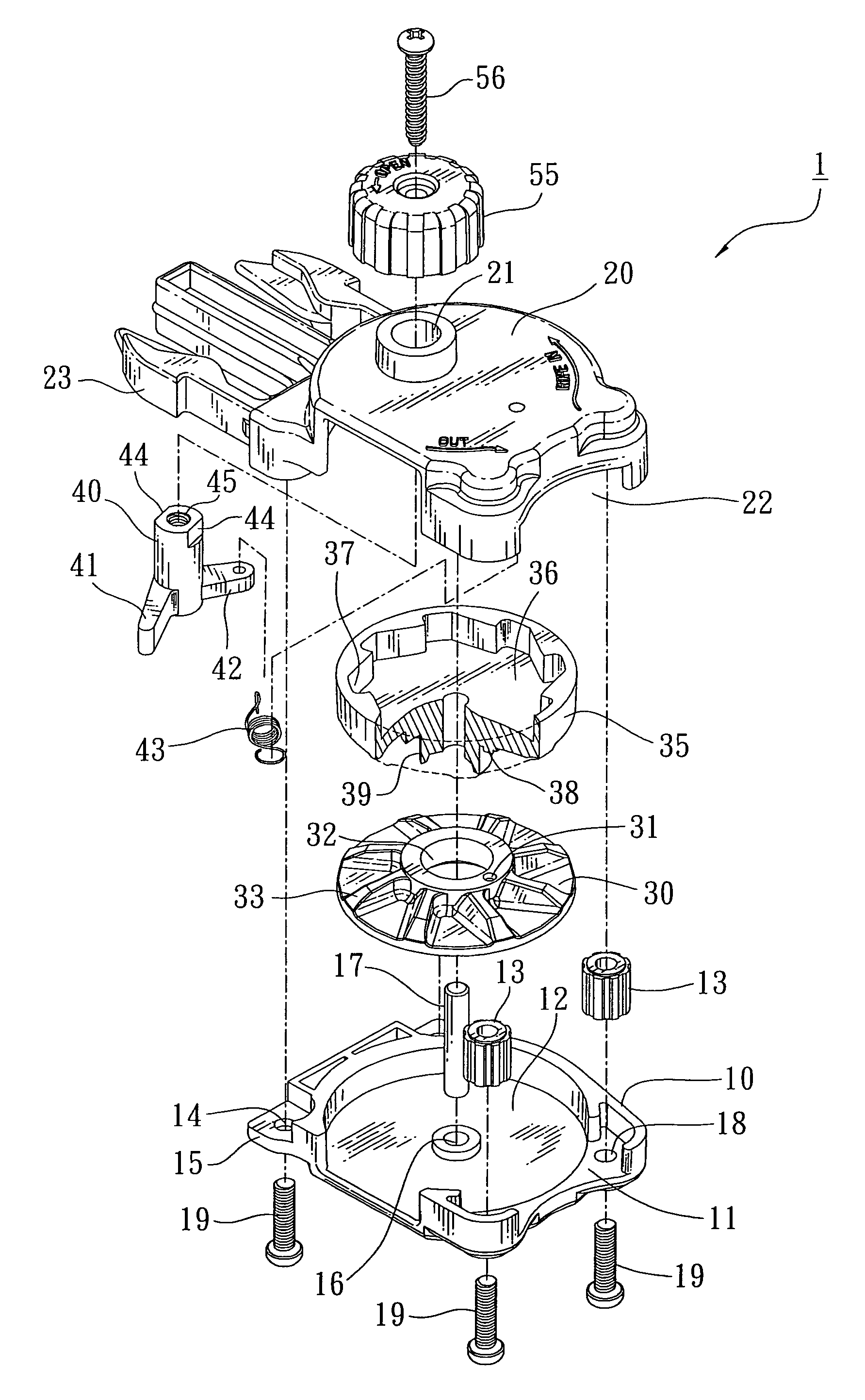
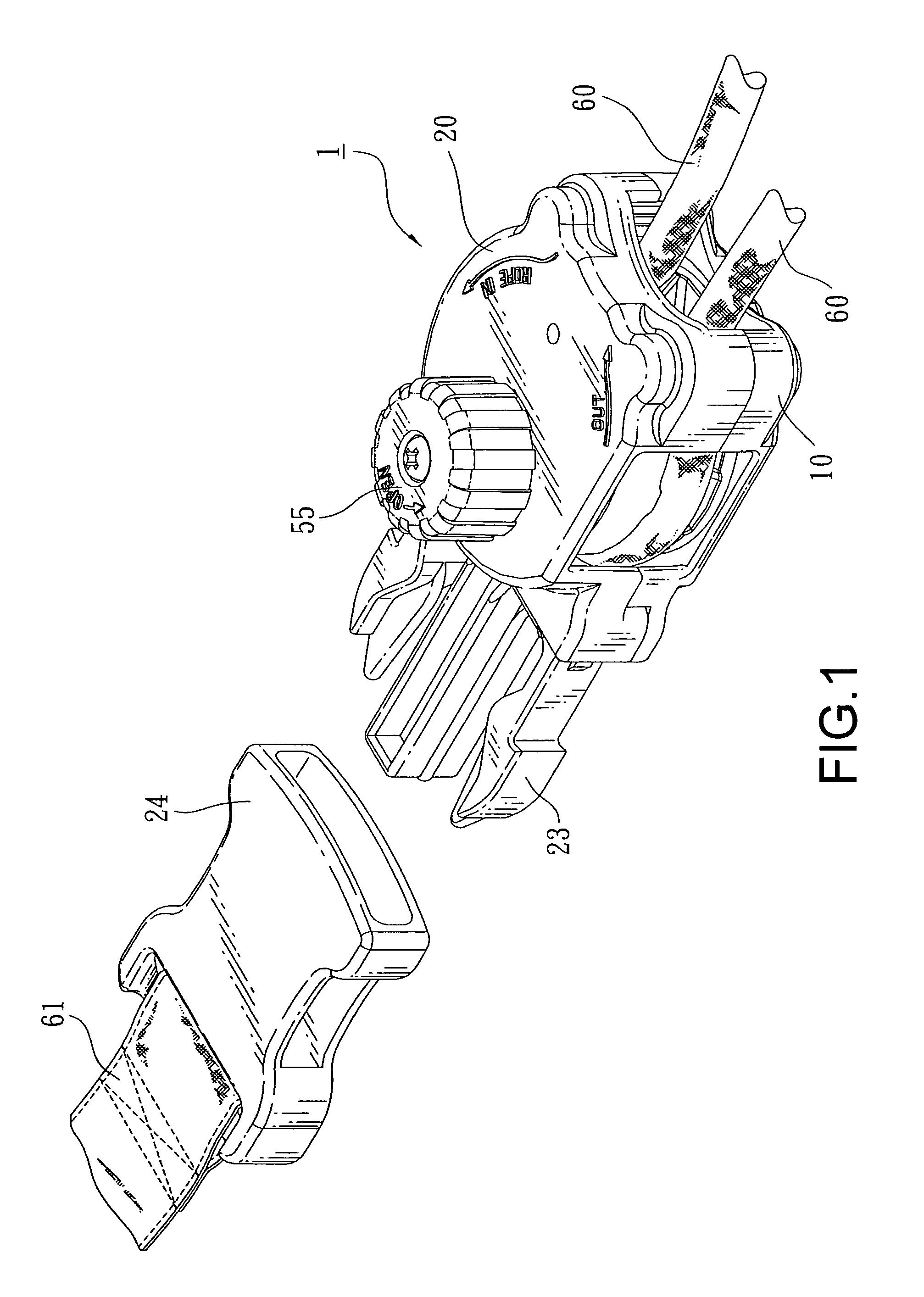
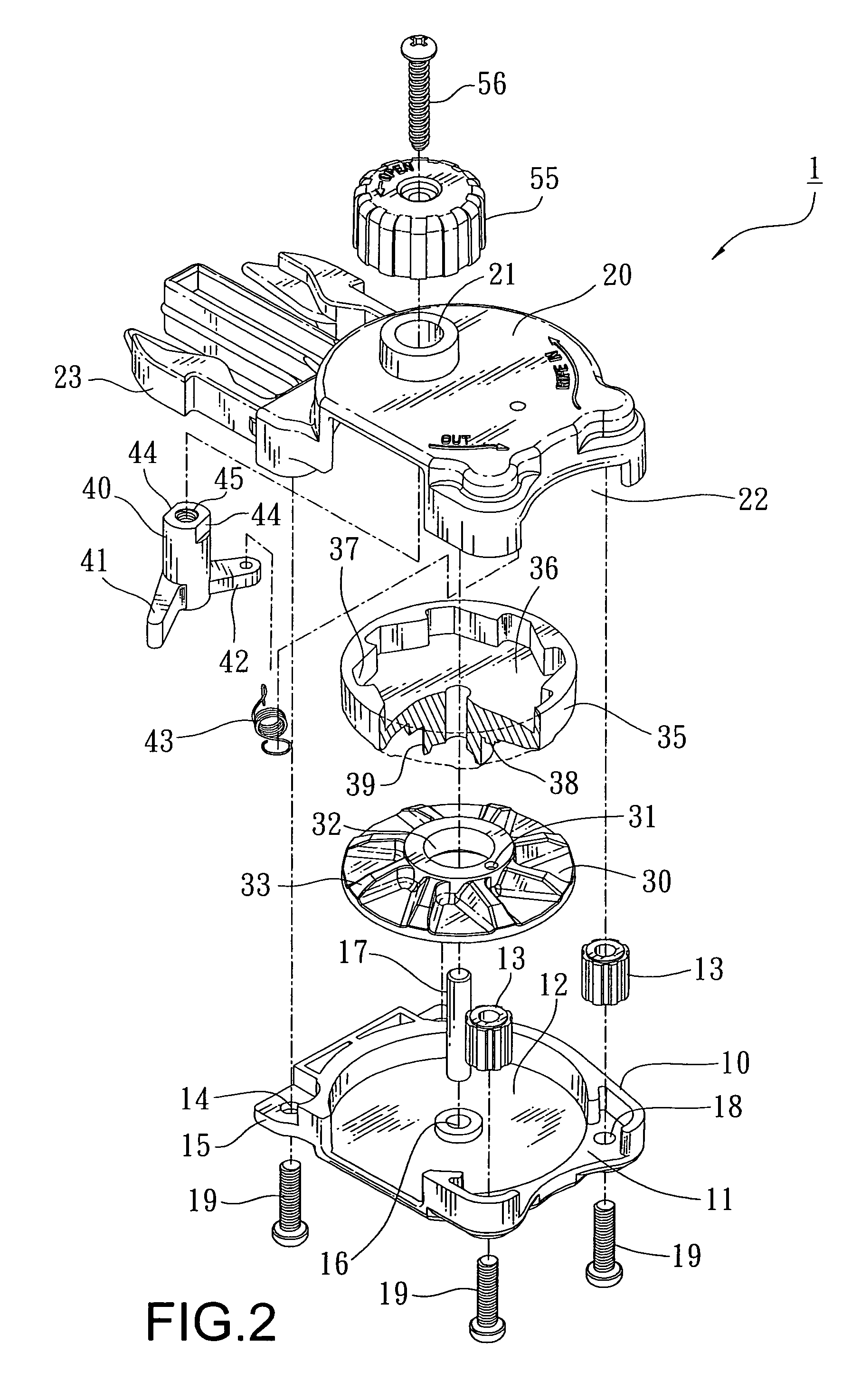
[0029]Referring to FIGS. 1 to 3, a tightening device 1 of the present invention comprises primarily a seat 10, a housing 20, a turntable 30, a wheel 35, and a lock bolt 40. A front end of the tightening device 1 is provided with a tenon 23 which can be inserted into a latching member with its locking belt 61 being provided with a latching slot 24, wherein a rope access 11 is located at a rear end of the seat 10, and two bores 18 are located at two sides of the access 11, respectively. The bores 18 allow for screws 19 to be penetrated from a bottom to a top, and two rollers 13 are located in the seat 10 for locking the screws 19 into the bores 28 (as shown in FIG. 4) at the opposite housing 20, so as to fix the rollers 13 at a left and a right side to the access 11 respectively, thereby preventing a rope 60 (as shown in FIG. 7) from being cracked by a friction in gliding. An indentation 12 is located at a central part in an interior of the seat 10, and a hole 16 is located at a cente...

second embodiment

[0038]Referring to FIGS. 11 to 13, a tightening device 1 of the present invention comprises primarily a seat 10, a housing 20, a roller 80, a shaft 85, and a knob 90.

[0039]An interior of the seat 10 is provided with a first indentation 101 and a second indentation 102, wherein the first indentation 101 can provide for an installation of the roller 80 and a center of the first indentation 102 is provided with a slot hole 103, whereas the second indentation 102 can provide for an installation of the shaft 85, and the second indentation 102 is also provided with a positioning hole 104. A side of bottom part of the seat 10 is provided with a rope entrance groove 105a and a rope exit groove 105b which are transfixed into the first indentation 101 and the second indentation 102. An inner side of the first indentation 101 is formed with an arc-shape groove channel 105c. In this embodiment, a front end of the seat 10 is provided with a tenon 106, a periphery of which is installed with bores...


PUM


Abstract

A latch-type tightening device structure comprises a body constituted by a seat and a housing, wherein an interior of the body is provided with a one-way braking mechanism which enables a rope to glide in one direction. A rope enters into and reeves around the tightening device by which the rope can be gliding in one direction latching. A front edge of the body is provided with a tenon or a latching slot, such that the tightening device can be quickly locked with a fitting part in application.

Description

BACKGROUND OF THE INVENTION[0001](a) Field of the Invention[0002]The present invention relates to a latch-type tightening device structure, and more particularly to a device structure for tightening a rope for a ship cover such that the ship cover will not be blown off by a strong wind after the structure is connected with the ship cover, and is provided with rollers for enabling a smooth gliding of the rope. The present invention can be applied to a device used to tighten an opening of a bag or the like, and is especially used in a cover for an automobile, a yacht, or an aqua-bike.[0003](b) Description of the Prior Art[0004]When a common vehicle such as a motorcycle, an automobile, a yacht, or an aqua-bike has to be parked and idle for a longer time, a dust-proof cloth or cover is usually used to cover it. This kind of cover can be used to prevent the vehicle from gaining dust or sand, and can prevent a casing of the vehicle from being cracked by exposure to the sun. As far as a tr...

Claims


Application Information

Patent Timeline
Patent Type & Authority Patents(United States)
IPC IPC(8): A44B11/06
CPCA44B11/006F16G11/00F16G11/04F16G11/10Y10T24/4093Y10T24/45524Y10T24/40Y10T24/21Y10T24/394Y10T24/4077Y10T24/4086F16G11/101F16G11/106
Inventor YANG, MING-SHUN
Owner FORMOSA SAINT JOSE
Features
  • R&D
  • Intellectual Property
  • Life Sciences
  • Materials
  • Tech Scout
  • Unparalleled Data Quality
  • Higher Quality Content
  • 60% Fewer Hallucinations
Learn More