High differential shifting tool

a shifting tool and high-discharge technology, applied in the direction of fluid removal, sealing/packing, borehole/well accessories, etc., can solve the problems of reducing the ability affecting the service life of the sleeve valve, so as to prevent significant stress and damage

Active Publication Date: 2009-07-07
BAKER HUGHES INC
View PDF9 Cites 49 Cited by
  • Summary
  • Abstract
  • Description
  • Claims
  • Application Information

AI Technical Summary

Benefits of technology

[0008]The invention provides devices and methods for opening and / or closing a sliding sleeve valve in order to prevent significant stress upon and damage to the fluid seals that are disposed between the outer housing and the sleeve member elements of the valve Preferred embodiments of the invention feature a shifting tool which carries a latching device and a fluid closure portion with sacrificial seals. In operation, the shifting tool is secured to the sleeve member with the latching device as the closure portion seals off across the fluid flow port of the sleeve member. The shifting tool is then moved to slide the sleeve member between open and closed positions. The shifting tool is then released from the sleeve member and the closure portion is removed from sealing contact with the fluid port of the sleeve member. The fluid seals between the housing and the sleeve member are protected since the rush of fluid associated with the release or capture of differential pressure will be diverted to the sacrificial seals.

Problems solved by technology

Operational problems arise where there is a significant pressure differential between the interior flowbore and the surrounding wellbore.
If this situation exists when the sleeve valve is being moved from a closed to an open position, or an open to a closed position, the seal rings are especially vulnerable to high pressure fluids passing through the aligned fluid ports.
The seal rings can be blown out or otherwise damaged during the process of opening or closing the sleeve valve.
Damage to the seal rings can seriously degrade or eliminate the ability of the sleeve valve to close off fluid flow into or out of the flowbore.
In such a situation, operating the valve between open and closed positions would be inadvisable and likely destroy the ability of the valve to function properly thereafter.

Method used


Image

  • High differential shifting tool
  • High differential shifting tool
  • High differential shifting tool

Examples


Embodiment Construction

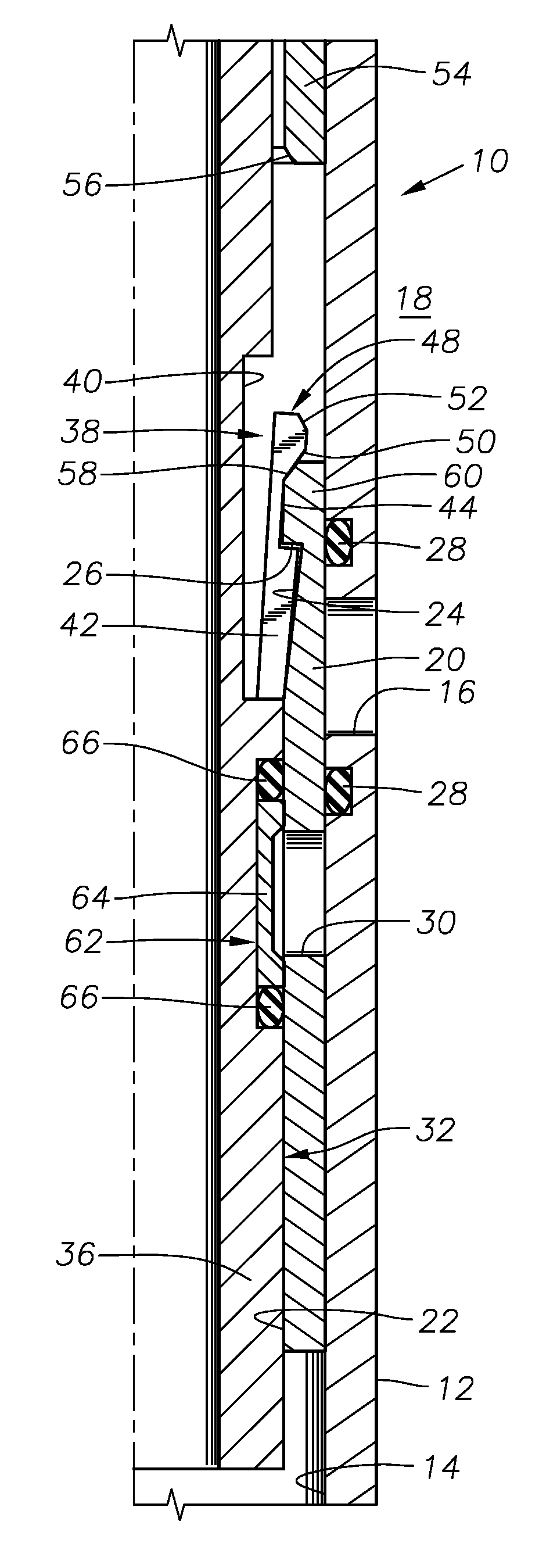
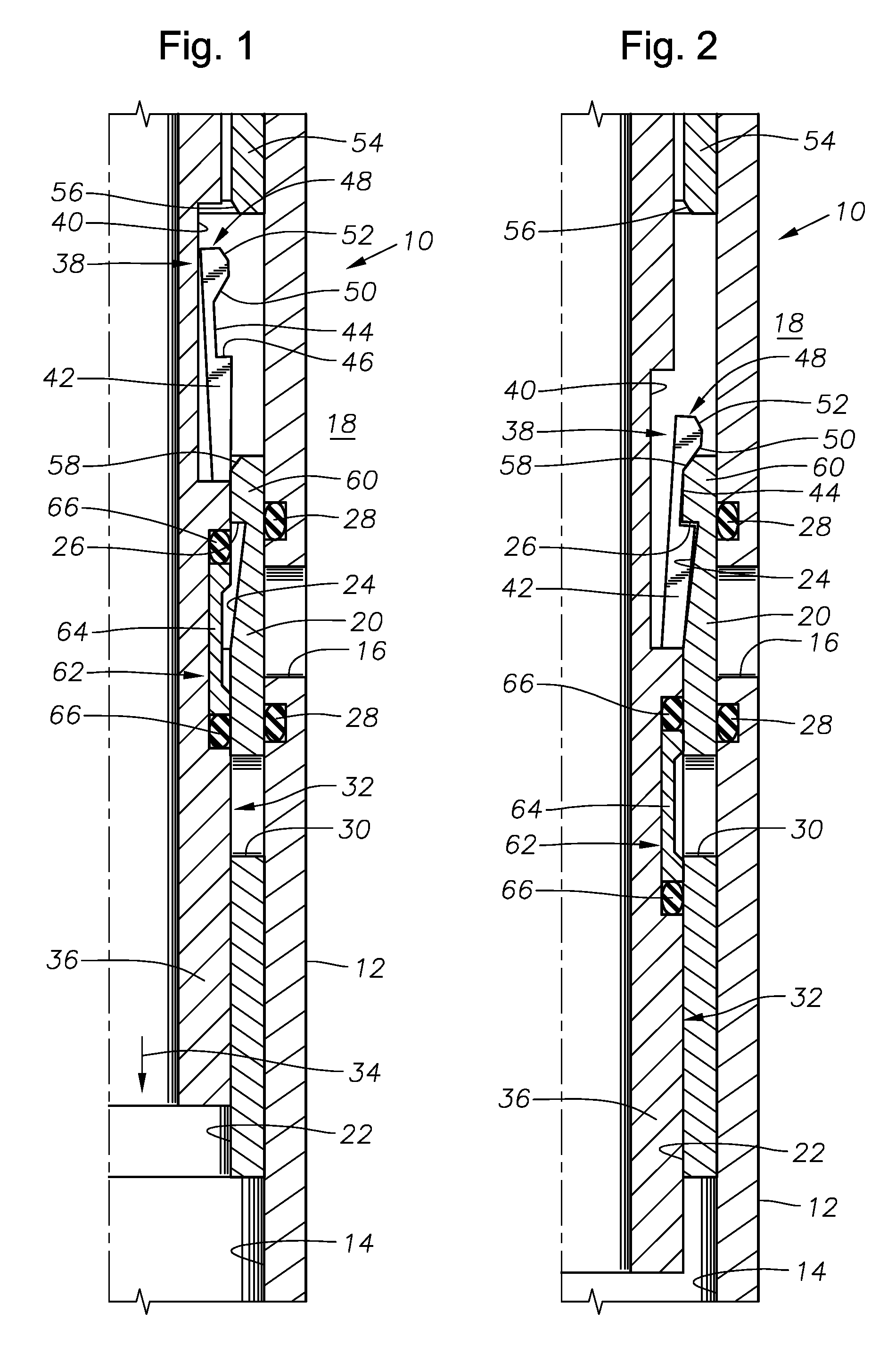
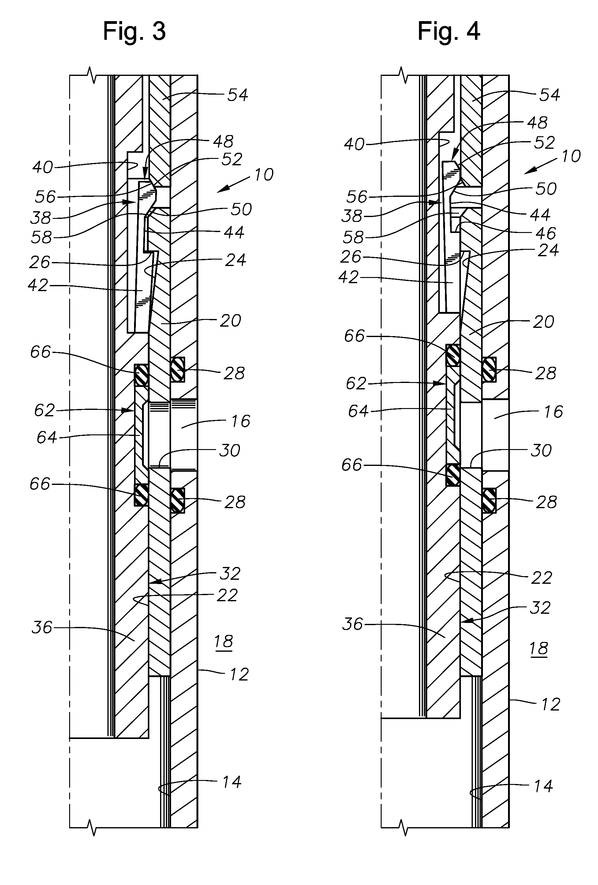
[0023]FIG. 1 depicts an exemplary sliding sleeve valve 10 having an outer housing 12 that defines a central flowbore 14 along its length. The housing 12 of the sliding sleeve valve 10 is typically incorporated into a production tubing string of a type known in the art for hydrocarbon production and disposed within a hydrocarbon production wellbore. An outer radial fluid flow port 16 is disposed through the housing 12 to permit fluid communication between the annulus 18 surrounding the housing 12 and the flowbore 14. An interior sliding sleeve member 20 is disposed within the flowbore 14 of the housing 12. The sleeve member 20 is axially moveable within the flowbore 14 with respect to the housing 12. A central axial pathway 22 is defined within the sleeve member 20. It is noted that the upper axial end of the pathway 22 of the sleeve member 20 contains a radially enlarged recess 24 that provides a downwardly-facing stop shoulder 26.

[0024]Annular fluid seals 28 are located on each axi...


PUM


Abstract

Systems and methods for opening and / or closing sliding sleeve valves while preventing significant stress upon and damage to the fluid seals that are disposed between the outer housing and the sleeve member elements of the valve. A shifting tool carries a latching device and a fluid closure portion with sacrificial seals. In operations the shifting tool is secured to the sleeve member with the latching device as the closure portion seals off across the fluid flow port of the sleeve member. The shifting tool is then moved to slide the sleeve member between open and closed positions.

Description

BACKGROUND OF THE INVENTION[0001]1. Field of the Invention[0002]The invention relates generally to methods and devices for operating siding sleeve devices used in subterranean wellbores and the like.[0003]2. Description of the Related Art[0004]Sliding sleeve valve devices are well known and widely used in downhole hydrocarbon production. Typically, these devices are made up of an outer tubular housing that defines an axial flowbore within. One or more radial fluid transmission ports are disposed through the outer housing. The outer tubular housing contains an inner sleeve member that is shiftable (typically axially) within the housing. The inner sleeve member also presents a radial fluid port through its body, which is selectively aligned with the fluid transmission port(s) in the housing as the sleeve is shifted within the housing. Typically also, there are annular seal rings located on either axial side of the fluid transmission port(s) to prevent fluid from flowing between the ho...

Claims


Application Information

Patent Timeline
Patent Type & Authority Patents(United States)
IPC IPC(8): E21B34/06E21B43/00
CPCE21B34/14E21B23/04
Inventor GOMEZ, ALFREDO
Owner BAKER HUGHES INC
Why Eureka
Try Eureka