System and apparatus for remote activation of implantable medical devices

a technology for implantable medical devices and remote activation, which is applied in the field of medical devices, can solve the problems of significant size addition to the implant device, large size, and significant impact on the size of the implantable medical device, and achieve the effect of reducing the voltage drop of the power sour

Inactive Publication Date: 2009-08-04
MEDTRONIC INC
View PDF14 Cites 12 Cited by
  • Summary
  • Abstract
  • Description
  • Claims
  • Application Information

AI Technical Summary

Benefits of technology

[0011]In a second exemplary embodiment, an integrated activation system is provided for an IMD sharing a power source therewith. The activation system includes a switching circuit and a sensing element coupled to the switching circuit. The switching circuit is configured to gate power from the power source to the IMD, and minimize a voltage drop to the power source while gating power to the IMD. The sensing element is configured to enable an operation interval of the switching circuit, and trigger a first state change in the switching circuit. The switching circuit is further configured to gate power to the IMD upon receipt of a pre-determined number of signals from the sensing element.

Problems solved by technology

The battery is oftentimes the largest component in the implanted medical device and therefore significantly impacts the size of the implantable medical device.
However, this conventional reed switch generally tends to be too large in size and thus adds significant size to the implant device.
Additionally, the reed switch may be susceptible to environmental effects (e.g., magnetic or mechanical) that may result in inappropriate sensor activation.
Smaller conventional reed switches, such as micro-electrical mechanical systems (MEMS) reed switches, may not pass sufficient current and are generally not suitable as a drop-in replacement for the conventional reed switch, such as previously described, where higher currents are used.
Additionally, MEMS reed switches are generally susceptible to the same environmental effects that may cause inappropriate activation in conventional reed switches.
Hall effect sensors typically require a stand-by current and are generally unsuitable as a means for turning a battery-powered device on or off.

Method used


Image

  • System and apparatus for remote activation of implantable medical devices
  • System and apparatus for remote activation of implantable medical devices
  • System and apparatus for remote activation of implantable medical devices

Examples


Embodiment Construction

[0017]The following detailed description is merely exemplary in nature and is not intended to limit the invention or the application and uses of the invention. Furthermore, there is no intention to be bound by any expressed or implied theory presented in the preceding technical field, background, brief summary, brief description of the drawings, or the following detailed description.

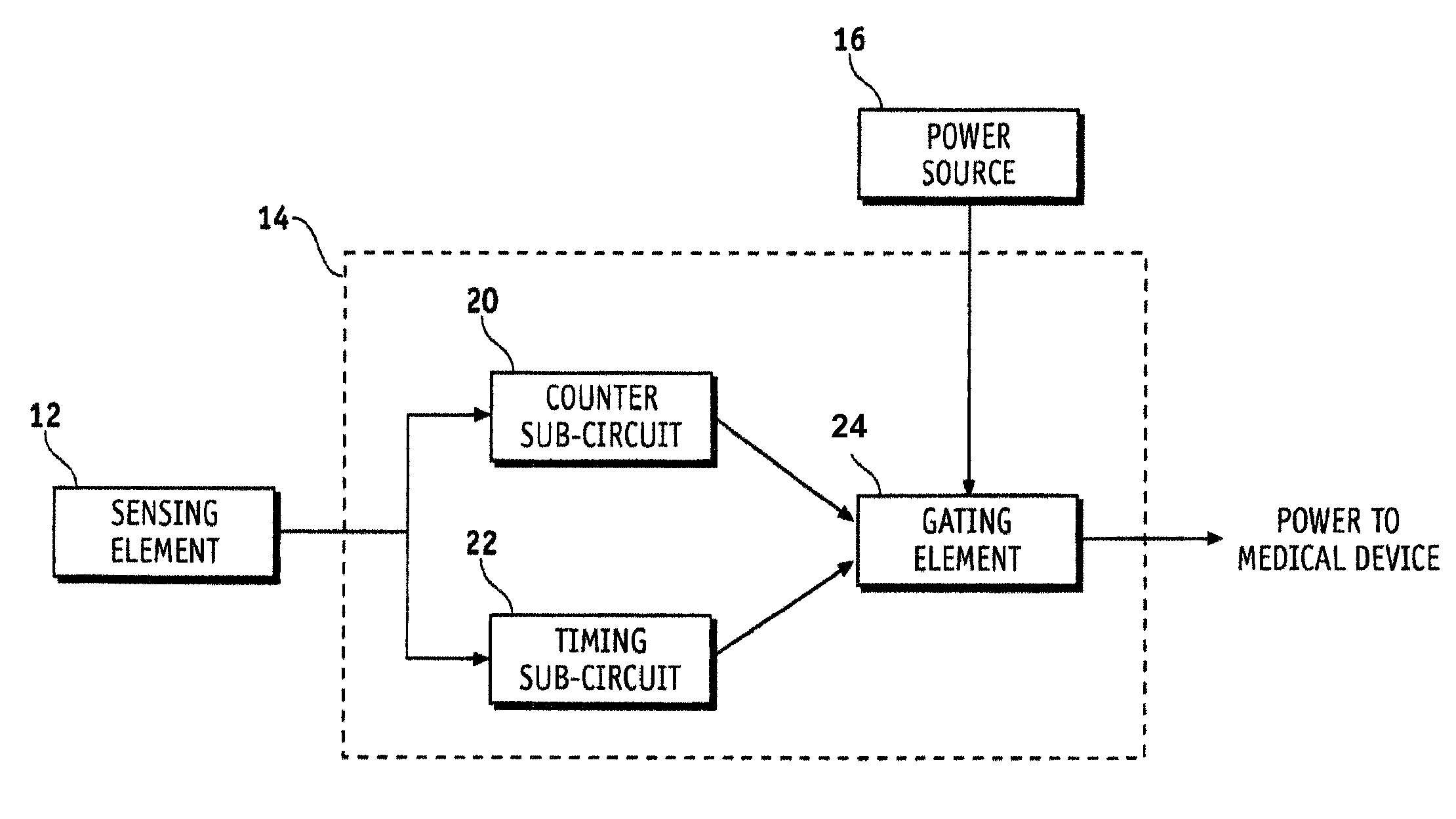
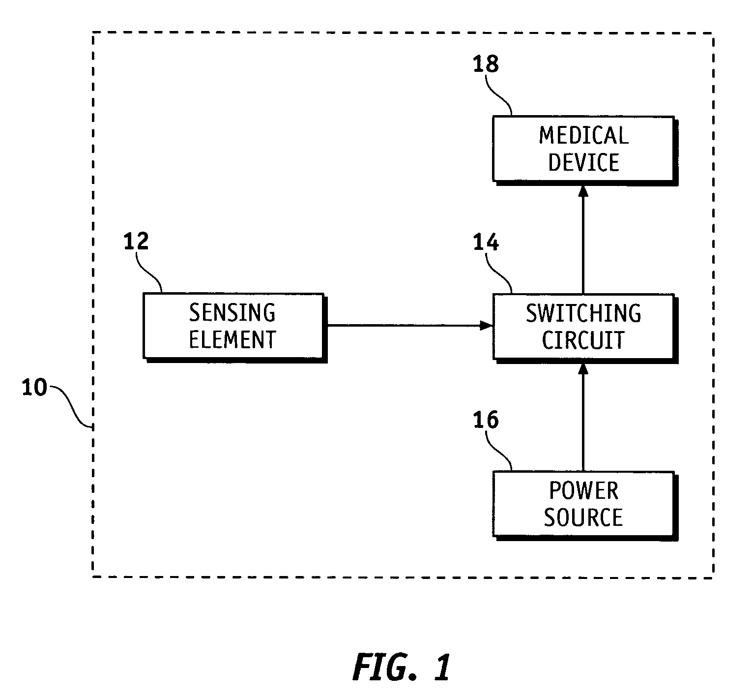
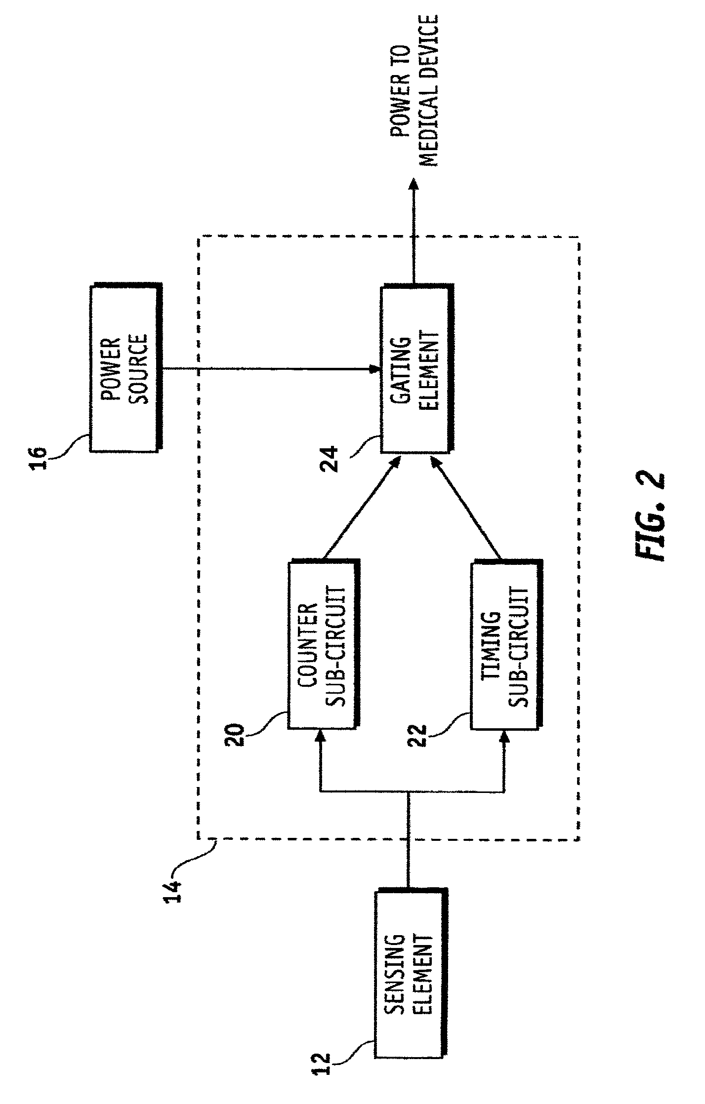
[0018]Referring to the drawings, FIG. 1 is a block diagram illustrating an implantable medical device 10 (IMD) in accordance with an exemplary embodiment of the present invention. The IMD 10 includes, but is not limited to, a sensing element 12, a switching circuit 14 coupled to the sensing element 12, and a power source 16 coupled to the switching circuit 14. A medical device 18 may be coupled to the switching circuit 14, such as a wireless sensor, leadless stimulator, drug delivery pump, or any number of implantable medical devices. Although not specifically detailed herein, additional components and c...


PUM


Abstract

An integrated activation system for an implantable medical device (IMD) sharing a power source, the activation system having a switching circuit and a sensing element coupled to the switching circuit. The switching circuit is configured to gate power from the power source to the IMD. The sensing element is configured to draw current from the power source of less than or equal to about 1 nA during inactivation, enable an operation interval of the switching circuit, and trigger a first state change in the switching circuit. The switching circuit further is configured to gate power to the IMD upon receipt of a pre-determined number of signals from the sensing element.

Description

CROSS-REFERENCE TO RELATED APPLICATION[0001]This application claims the benefit of U.S. Provisional Application No. 60 / 495,901, filed Aug. 18, 2003.TECHNICAL FIELD[0002]The present invention relates generally to medical devices, and more particularly to controlling activation of implantable medical devices.BACKGROUND[0003]Implantable medical devices that are minimally invasive and self-contained are increasingly popular as modes for improving medical care. For example, wireless sensors, leadless stimulators, and drug delivery pumps are some implantable medical devices that are becoming pervasive tools used in medical treatment. Some of these devices are powered by batteries and may operate continuously until the battery is depleted or may intermittently operate with spaced apart “sleep” intervals so as to extend battery longevity.[0004]In designing implantable medical devices, a trade-off is commonly encountered between competing needs for a small device size and for a battery with ...

Claims


Application Information

Patent Timeline
Patent Type & Authority Patents(United States)
IPC IPC(8): A61N1/00A61K9/22A61N1/08
CPCA61N1/378A61N1/08
Inventor DINSMOOR, DAVID A.CARNEY, JAMES K.
Owner MEDTRONIC INC
Why Eureka
Try Eureka